Do you have a question about the Luxman M-900u and is the answer not in the manual?
Advice on unit placement for proper ventilation and heat dissipation.
Guidelines for safe connection of components and speakers to prevent damage.
Explains sound muting and the unit's protection circuit functions.
Covers repair, cleaning, and general safety warnings regarding the unit's weight.
Describes the amplifier's circuit structure and rated output power.
Explains the ODNF feedback circuit for high-speed slew rate and pure sound.
Details the BTL mode for a high-quality, high-power monaural amplifier.
Highlights input switching, phase selection, quality relays, and the high-inertia power supply.
Focuses on speaker relay impedance reduction and internal OFC wiring for signal transmission.
Details PCB treatment for dielectric effect and the analog power meters.
Covers chassis construction, speaker terminals, AC inlet, and vibration-damping insulators.
Identifies and explains the front panel's indicators and controls.
Explains standby/operation indicators and the main operation switch.
Explains how to select input sources and indicates the selected input.
Covers display modes and BTL monaural operation indication.
Explains the function and operation of the unit's power meters.
Identifies and explains connectors and switches on the rear panel.
Explains switches for stereo/BTL mode and the main power.
Details phase inversion, signal ground, and unbalanced input terminals.
Explains balanced input and speaker terminals for various connection modes.
Covers AC power input and remote control connections.
Instructions for restoring the unit's settings to factory defaults.
Crucial steps before connecting, including power supply setup.
Guides connecting input devices and remote control amplifiers.
Detailed instructions for connecting speakers in stereo and BTL modes, with safety advice.
Illustrates the wiring for normal stereophonic reproduction.
Shows the wiring for BTL monaural reproduction using two units.
Illustrates wiring for bi-amplification or stereophonic reproduction with multiple amplifiers.
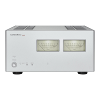
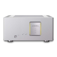
This document serves as the owner's manual for the Luxman M-900u Stereo Power Amplifier, providing comprehensive information on its features, functions, connections, and maintenance.
The M-900u is a high-performance stereo power amplifier designed for audiophiles seeking exceptional sound quality and robust power delivery. Its core function is to amplify audio signals from a preamplifier or control amplifier and drive loudspeakers with precision and power.
The amplifier offers versatile input options, including both unbalanced RCA (LINE) and balanced XLR (BAL LINE) terminals. A 2-channel input selector on the front panel allows users to easily switch between these input types, accommodating various source components. The XLR terminals, manufactured by Neutrik, support high-grade balanced signal transmission, which is beneficial for minimizing noise over longer cable runs. For balanced inputs, a phase inverter switch (BAL LINE PHASE) on the rear panel allows users to adjust the phase to match the input device, ensuring proper sound reproduction.
The M-900u supports both stereo and BTL (Bridged Transless) monaural connection modes, selectable via a switch on the rear panel. In stereo mode, it operates as a conventional two-channel amplifier, driving a pair of loudspeakers. In BTL (MONO) mode, two M-900u units can be combined to function as high-power monaural amplifiers, significantly increasing the output power for a single channel. This configuration is ideal for demanding speaker systems or for achieving a more dynamic soundstage. When in BTL mode, only the left input channel of the M-900u is active, and signals from the right input are not used. For stereo playback in BTL mode, a second M-900u unit is required, with one unit handling the left channel and the other handling the right.
Speaker connections are made via large, robust terminals designed to accommodate Y-lugs and extra-thick speaker cables, ensuring secure and low-resistance connections. The terminals are laid out with identical characteristics for both right and left channels. Users must pay careful attention to polarity and channel assignment during connection to avoid phase issues or reversed channels, which can negatively impact sound localization and bass response. The manual specifically warns against using speaker selection switch boxes that connect the speaker terminal to a common ground terminal when in BTL (MONO) mode, as this can cause a short circuit and activate the protection circuit.
The amplifier features a time muting circuit that delays audio output for approximately 15 seconds after power-on. This prevents sudden loud noises and protects speakers and the amplifier from potential damage during startup. Users are advised to set the volume control of their input device to a low level before the muting circuit is canceled.
A protection circuit is integrated to safeguard the amplifier and connected speakers from overcurrent, abnormally high temperature, and DC drift. If activated, the output to the speaker terminals is shut off, and the standby indicator lights up. If this occurs frequently, users are advised to consult their dealer.
The front panel includes a standby indicator (STAND BY) and an operation indicator (OPERATION) to show the unit's status. The operation switch (OPERATION) transitions the unit from standby to active mode.
A high-grade analog meter with shower light is prominently featured on the front panel, indicating the output level to the speakers in decibels. The display switch (DISPLAY) allows users to control the meter's light and display, with different options available depending on whether the unit is in STEREO or BTL (MONO) mode. In stereo mode, both meters display the L and R channel levels, respectively. In BTL (MONO) mode, only the left meter indicates the level. The display settings are memorized for both STEREO and BTL (MONO) modes.
Remote input terminals (REMOTE IN) allow the M-900u to be linked with a compatible Luxman control amplifier (e.g., C-900u) using a dedicated remote cable. This enables synchronized power-on/standby operation with the control amplifier.
For cleaning, the manual recommends using a soft cloth. For stubborn dirt, a soft cloth with a small amount of neutral detergent can be used, followed by wiping with a dry cloth. Users are explicitly warned against using solvents like benzine or thinner, as these can damage the unit's exterior.
The manual also includes a troubleshooting guide to help users identify and resolve common issues, such as no power, no sound, or unbalanced sound. This guide provides solutions for problems related to power connections, input selection, cable connections, BTL/stereo mode settings, and display settings.
The device is designed with a "loopless chassis" construction to eliminate increased ground impedance caused by chassis current, contributing to cleaner sound. It also incorporates "cast-iron insulators" to cut out unnecessary external vibration and provide strong support for the unit's substantial weight.
The internal wiring uses Luxman's original OFC (Oxygen-Free Copper) wires with spiral wrap shielding and a non-plating process on the core wire for smooth signal transmission. The audio circuit board features 100µm thick copper foil and gold plating instead of resist, eliminating dielectric effects.
The power supply circuit is a "high-inertia power supply" combining a large-capacity El-core-type power transformer with rectangular copper winding wires and customizable 20,000µF × 4 block capacitors, ensuring stable and robust power delivery.
The amplifier's "4 x 2 output structure" utilizes two modules of 4-parallel push-pull amplification circuits, each structured with 3-stage Darlington, for each channel, contributing to its high power output and stability.
The "ODNF (Only Distortion Negative Feedback)" circuit, in its 4.0 version, is a key feature that feeds back only distortion components generated during amplification. This design aims to maintain the pure sound quality of a main amplifier that is almost non-feedback, achieving low impedance and a high S/N ratio. The input stages of the error detection circuit are 3-parallelized to further improve distortion and noise performance.
The "4-parallel speaker relay" design reduces the impedance of speaker output lines by using a 4-parallel contact structure with low resistance values for each channel.
Schottky barrier diodes, manufactured by Nihon Inter Electronics Corporation, are used in the power supply rectifier circuit. These diodes offer less switching noise and higher conversion efficiency, contributing to the overall performance and reliability of the unit.
| Type | Power Amplifier |
|---|---|
| Instantaneous Maximum Output Power (4Ω) | 600W + 600W |
| Total Harmonic Distortion | 0.03% |
| Frequency Response | 20Hz-20kHz |
| Frequency Response (Extended) | 5 Hz - 100 kHz |
| Dimensions | 440 mm |