INSTALLATION
Fittings and Valves:
1. 90° elbows directly into pump intake & discharge are NOT allowed.
2. Installing gate valves on suction and discharge pipes is an important
part of any flooded suction system, as it allows for maintenance and
other activities to be carried out more easily. However, the suction gate
valve should not be placed any closer than five times the diameter of
the suction pipe.
3. Using a check valve in the discharge line is highly recommended for
any application of this pump where there is significant plumbing height
after the pump.
4. It is important to install check valves when plumbing in parallel with
another pump to ensure proper functioning. Check valves help to
prevent reverse rotation of the impeller and motor.
Electrical Installation:
READ THIS INSTRUCTION BEFORE OPERATION
RISK OF ELECTRICAL SHOCK OR ELECTROCU-
TION.
It is essential that the pump MUST be installed by a qualified and licensed
electrician, or a certified service professional, in accordance with the
National Electrical Code and all applicable local codes and ordinances.
When the pump is not properly installed, it can create an electrical hazard,
which can potentially lead to death or serious injury, due to electric shock
or electrocution.
It is essential to always disconnect power to the pump at the circuit breaker
before servicing the pump. Failing to do so can have catastrophic conse-
quences for those involved: Electric shock and property damage are the
least of the dangers; Death or serious injury to service people, pool users,
or even bystanders can occur.
The pump can automatically accept a single phase, 115/208-230V, 50 or
60 Hz input power and No wiring change is required. The power connec-
tions (below picture) are capable of handling up to 10 AWG solid or strand-
ed wire.
DANGER
INSTALLATION:
It is essential to only use a qualified professional to ensure a safe and
successful installation. Failure to follow this instructions correctly could
result in serious injury or property damage.
LOCATION:
NOTE: It is important to note that when installing this pump, it should not
be placed within an outer enclosure or underneath the skirt of a hot tub or
spa, unless it is marked accordingly.
Note: it is essential to ensure that the pump is mechanically secured to the
equipment pad for proper functioning.
Make sure the pump can match the below requirements:
1. It is important to install the pump as close to the pool or spa as possible.
This will reduce friction loss and improve the overall efficiency of the
pump. To further reduce friction loss and improve efficiency, it is recom
mended to use short, direct suction and return piping.
2. It is important to ensure that there is a minimum of 5' (1.5 m) between
the inside wall of the pool and spa and any other structures. For any
Canadian installations, a minimum of 9.8' (3 m) from the inside wall of
the pool must be maintained.
3. It is important to install the pump at least 3' (0.9 m) away from the heater
outlet.
4. It is important to remember to not install the self-priming pump more
than 8' (2.6 m) above the water level.
5. it is important to choose a well-ventilated location that is protected from
excess moisture.
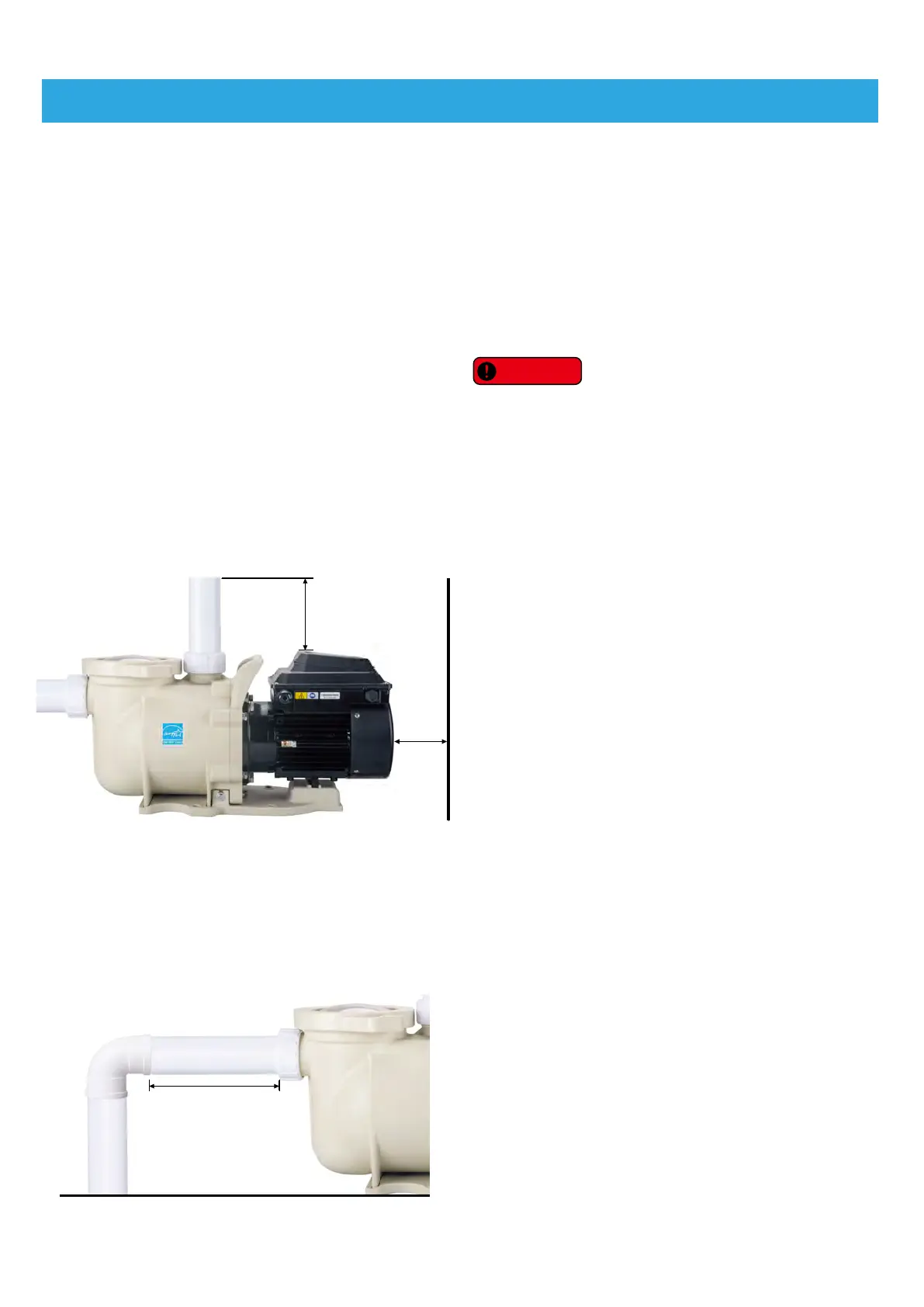
6. Please keep at least 3” from rear of motor and 6” from the top of control
pad for easy maintenance and repair.
PIPING:
1. The Piping diameter on the intake of the pump should be the same or
larger than the one of the discharge.
2. The shorter of plumbing on the suction side is better.
3. A valve on both suction and discharge lines is recommended for easy
maintenance and repair.
4. Any valve, elbow or tee installed in the suction line should be at least five
(5) times of suction line diameter from the discharge port. For example,
2” pipe requires 10” straight line before the suction port of the pump, as
below drawing.
6 Inches(15.2cm)
Minimum
3 Inches
(7.62cm)
Minimum
5 times of suction
line diameter
SHP130-VS, SFP220-VS, SWP390-VS Variable Speed Pumps Instruction
For more details and video, please visit www.lingxiao.com.cn
-5-