become operational. In ON mode, when AC power is applied the Aurora will be ready to use. ON is
the ideal setting when a single power switch is used to turn on an equipment rack.
To activate, hold the POWER button while connecting AC power. PLEASE NOTE: After the mode is
changed the unit must be put into standby mode to save this setting before power is removed again.
This function requires firmware revision 11 or higher in order to operate.
Restore Defaults
This command returns the Aurora to its factory default condition. SYNC SOURCE, ROUTING,
TRIM, AES states, etc. will all be impacted. This is a useful diagnostic step whenever performance
problems are encountered. To activate, press the SAMPLE RATE button while AC Power is applied.
This function requires firmware revision 11 or higher in order to operate.
Verify Firmware Revision
This command will display the current firmware version of the Aurora. In standby mode, press the
TRIM and POWER buttons simultaneously. The LEDs in the PEAK METER display will blink, and
the LED over one or two channels will flash repeatedly. This is the number of the active firmware
version. This function requires firmware revision 13 or higher in order to operate.
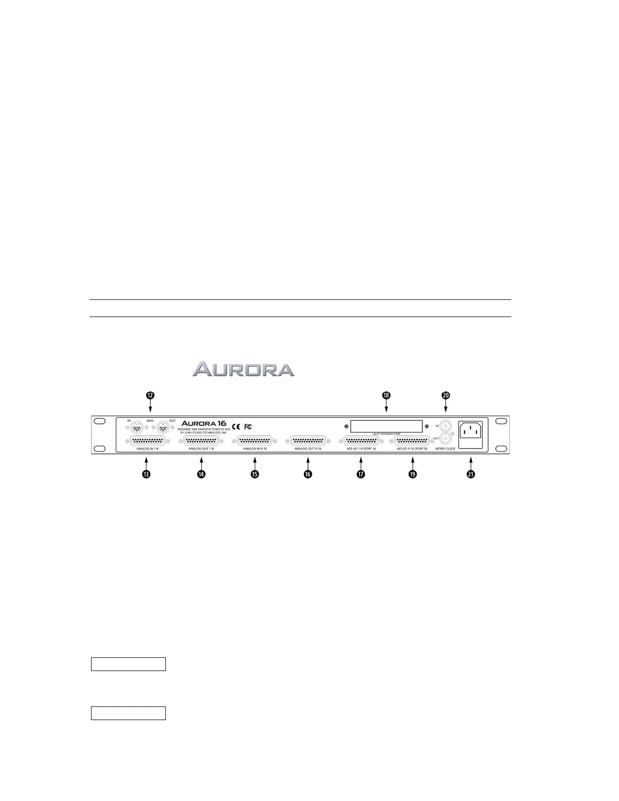
2.3 Back Panel Connections
The Aurora has been designed for maximum flexibility to integrate smoothly into today’s studio
environment. Following is a guide to the physical connectors on the Aurora back panel.
BACK PANEL
(pictured Aurora 16)
d MIDI IN and MIDI OUT
These connectors provide connectivity to external equipment via standard 5-pin din MIDI cables.
When connected to a computer with an installed MIDI Interface, the Aurora firmware can be updated
remotely, or the MIDI version of the remote control software can be used.
f ANALOG IN (1-8)
25-pin D-Sub connector provides access to Analog Inputs 1-8. Please refer to Section 2.4 Cable
Connections for more information about compatible cable sets.
g ANALOG OUT (1-8)
25-pin D-Sub connector provides access to Analog Outputs 1-8
h ANALOG IN (9-16)
25-pin D-Sub connector provides access to Analog Inputs 9-16.
Aurora 8 This connector is not present.
j ANALOG OUT (9-16)
25-pin D-Sub connector provides access to Analog Outputs 9-16.
Aurora 8 This connector is not present.
Page 8