2.4 Cable Connections
Compatible cables for the Aurora analog and digital I/O ports are available directly through Lynx. The
25-pin D-Sub connectors on Aurora conform to industry-standard pin configurations, so that off-the-
shelf cable solutions are available from third party suppliers should custom lengths or connector types
be required.
Lynx Cable Aurora Port Connectors Connectors Length Use
CBL-AOUT85 Analog Out DB25 XLR Male X 8
16.4’
(5M)
8-Channels Balanced
Analog Out
CBL-AIN85 Analog In DB25 XLR Female X 8
16.4’
(5M)
8-Channels Balanced
Analog In
CBL-AES1605 Digital I/O DB25 HD26
16.4’
(5M)
8-Channels AES/EBU
In/Out to AES16
CBL-DIGY85 Digital I/O DB25
XLR Male X 4,
XLR Female X 4
16.4’
(5M)
8-Channels AES/EBU
In/Out
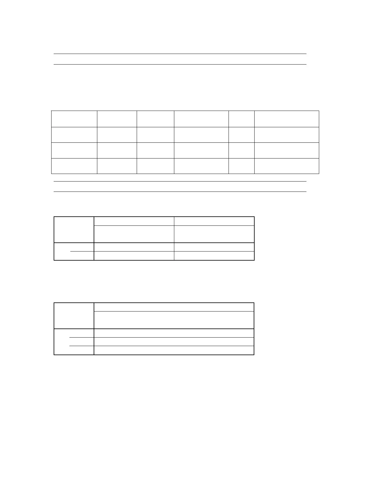
2.5 Connector Pin Outs
For third-party cable solutions Digital cables should adhere to the Yamaha MY8AE96 YGDAI Digital
I/O pinout:
Digital Input Channels Digital Output Channels
1-2 3-4 5-6 7-8 1-2 3-4 5-6 7-8
Signal
9-10 11-12 13-14 15-16 9-10 11-12 13-14 15-16
Hot 1 2 3 4 5 6 7 8
Pin
Cold 14 15 16 17 18 19 20 21
GND: 10, 12, 13, 22, 23, 24, 25
Unused: 9, 11
For third-party cable solutions Analog cables should conform to the Tascam DA-88 Analog I/O pinout:
Analog Channels
1 2 3 4 5 6 7 8
Signal
9 10 11 12 13 14 15 16
Hot 24 10 21 7 18 4 15 1
Cold 12 23 9 20 6 17 3 14
Pin
GND 25 11 22 8 19 5 16 2
Unused: 13
Page 10