Do you have a question about the M5Stack M5STICKC PLUS and is the answer not in the manual?
Instructions on downloading and preparing the M5Burner firmware burning tool for your operating system.
Steps for burning firmware onto the M5 device using the M5Burner application.
Describes methods for configuring the device's WiFi connection, including burn configuration.
Details the process of pairing the device's API Key within the UIFlow programming environment.
Provides instructions for using USB programming mode with the M5 device.
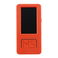
The M5StickC PLUS is an ESP32-based board designed for a variety of applications, offering a compact and versatile platform for development. It integrates a range of hardware components to provide comprehensive functionalities, making it suitable for projects requiring Wi-Fi, Bluetooth, display, motion sensing, and infrared communication.
The core of the M5StickC PLUS is the ESP32-PICO-D4 module, a System-in-Package (SiP) solution that provides complete Wi-Fi and Bluetooth capabilities. This module integrates a 4-MB SPI flash, a crystal oscillator, filter capacitors, and RF matching links, ensuring a robust and reliable wireless connection. The ESP32-PICO-D4 features two low-power Xtensa 32-bit LX6 MCUs, along with on-chip memory comprising 448-KB of ROM for kernel function calls, 520 KB of instruction and data storage SRAM (including 8 KB RTC flash memory), 8 KB RTC flash memory for Deep-sleep mode data storage, and 8 KB RTC slow memory accessible by a coprocessor in Deep-sleep mode. Additionally, it includes 1 kbit of eFuse, with 256 bits for system-specific data (MAC address and chip set) and 768 bits reserved for user programs, including flash program encryption and chip ID.
The device is equipped with a 1.14-inch TFT screen, driven by Sitronix's ST7789, offering a resolution of 135 x 240 pixels. This color screen operates within a voltage range of 2.5V to 3.3V, providing clear visual feedback for various applications.
For motion tracking, the M5StickC PLUS incorporates an MPU-6886 IMU. This 6-axis Motion Tracking device combines a 3-axis gyroscope and a 3-axis accelerometer in a small 3 mm x 3 mm x 0.75 mm 24-pin LGA package, enabling precise orientation and movement detection.
An IR transmitter is included, allowing the device to send infrared signals, which can be useful for remote control applications or other infrared communication tasks. A red LED provides visual indicators for status or alerts.
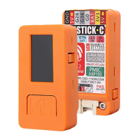
The M5StickC PLUS features a single button for user input, simplifying interaction with the device. A GROVE interface is provided for easy expansion, offering a 4-pin connector with a 2.0mm pitch. This interface connects to GND, 5V, GPIO32, and GPIO33, allowing for seamless integration with a wide range of GROVE modules.
Power management is handled by X-Powers's AXP192 chip, which supports an operating voltage range of 2.9V to 6.3V and a charging current of 1.4A. This ensures efficient power delivery and battery charging. The device also includes a battery for portable operation.
A Type-C-to-USB interface supports the USB2.0 standard communication protocol, facilitating data transfer and firmware updates.
The M5StickC PLUS also supports external QSPI flash and static random access memory (SRAM), with hardware-based AES encryption to protect user programs and data. The ESP32 can access external QSPI Flash and SRAM by caching, mapping up to 16 MB of external Flash code space into the CPU for 8-bit, 16-bit, and 32-bit access and execution. Up to 8 MB of external Flash and SRAM can be mapped to the CPU data space, supporting 8-bit, 16-bit, and 32-bit access. Flash supports read operations, while SRAM supports both read and write operations. The integrated 4 MB SPI Flash in the ESP32-PICO-D4 can also be mapped into CPU space, supporting various access widths and code execution. GPIO6, GPIO7, GPIO8, GPIO9, GPIO10, and GPIO11 are used for the integrated SPI Flash and are not recommended for other functions.
The device integrates a 40 MHz crystal oscillator for precise timing.
The M5StickC PLUS is designed for ease of use, from initial setup to advanced programming. It supports various power-saving modes to optimize battery life, including Active Mode (RF chip operating), Modem-sleep mode (CPU runs, Wi-Fi/Bluetooth baseband and RF configured), Light-sleep mode (CPU suspended, RTC and memory/ULP coprocessor operate), Deep-sleep mode (only RTC memory and peripherals work, ULP coprocessor can work), and Hibernation Mode (8 MHz oscillator and ULP coprocessor disabled, RTC memory power supply cut off, only RTC clock timer and some RTC GPIO work). These modes allow developers to balance performance and power consumption based on application requirements.
For programming, the M5StickC PLUS can be used with UIFlow, a visual programming platform. The UIFlow Quick Start guide outlines the process of burning firmware and configuring Wi-Fi. Users can download the M5Burner tool for their operating system (Windows, macOS, Linux) to flash the device. The burning process involves selecting the device type, firmware version, and then connecting the M5 device via a Type-C cable. Wi-Fi information can be configured during the burning stage or later via AP hotspot configuration.
AP hotspot configuration involves holding the power button to turn on the machine. If Wi-Fi is not configured, the device automatically enters network configuration mode. Users can also manually enter this mode by clicking the Home button after the UIFlow Logo appears, navigating to "Setting," and then "WiFi Setting." Once in configuration mode, users connect their mobile phone to the device's hotspot, open a browser to scan a QR code or access 192.168.4.1, and enter their Wi-Fi credentials. After configuration, the device restarts and enters programming mode. It is important to note that special characters like "space" are not allowed in Wi-Fi information.
The device supports "Network Programming Mode," which is a docking mode between the M5 device and the UIFlow web programming platform. In this mode, the screen displays the network connection status, and a green indicator signifies readiness to receive program pushes. After initial Wi-Fi setup, the device automatically restarts into this mode. To re-enter, users can press button A in the main menu to select programming mode.
API Key pairing is crucial for communication between the M5 device and the UIFlow web platform. Users visit flow.m5stack.com, click the setting button, enter the API Key displayed on their device, select the hardware (Stick-C), and save. A successful connection prompt indicates readiness for programming.
A simple program to light up the LED involves dragging the LED block, splicing it into the setup initialization program, and clicking the Run button in UIFlow.
For offline programming, the UIFlow Desktop IDE is available for Windows, macOS, and Linux. This offline version provides a responsive program push experience without requiring a network connection.
When using the UIFlow Desktop IDE, the application automatically detects if a USB driver (CP210X) is installed. If not, it prompts the user to install it. (M5StickC does not require a CP210X driver, so users can skip this step if desired). After driver installation, the IDE automatically pops up a configuration box. Users then connect the M5 device via a Type-C data cable, restart the device by clicking the power button, and quickly select "USB mode" from the menu. In the IDE, users select the corresponding COM port and programming device, then click OK to connect.
The M5StickC PLUS also features BLE UART functionality, allowing for Bluetooth connection and passthrough services. This enables the device to send and receive data over Bluetooth, facilitating wireless communication with other devices.
The M5StickC PLUS is designed for durability and ease of maintenance. The board is constructed from PC+ABC materials, providing a robust enclosure.
For firmware updates or troubleshooting, the M5Burner tool allows users to erase the flash memory. This is particularly useful when burning firmware for the first time or if the program runs abnormally. However, for subsequent firmware updates, erasing is not necessary unless Wi-Fi information needs to be deleted or the API Key refreshed.
The device's power management chip (AXP192) ensures stable power delivery and efficient battery charging, contributing to the longevity of the battery.
The USB Type-C interface provides a standard and reliable connection for both data transfer and power, simplifying connectivity and reducing wear and tear compared to older USB standards.
The M5StickC PLUS is designed to comply with FCC regulations, ensuring it operates within specified radio frequency limits and minimizes interference with other devices.
To power on the device, users press and hold the side power button for two seconds. To power off, they press and hold for more than six seconds. The device can switch to photo mode via the Home screen, displaying an avatar from the camera on the TFT screen. For continuous operation, the USB cable must be connected, while the lithium battery provides short-term storage to prevent power failure.
| Microcontroller | ESP32-PICO-D4 |
|---|---|
| Chipset | ESP32 |
| CPU Cores | Dual-core |
| Clock Speed | 240 MHz |
| Flash Memory | 4 MB |
| RAM | 520 KB |
| Input Voltage | 5V |
| Operating Voltage | 3.3V |
| IR Transmitter | Yes |
| Microphone | Yes |
| IMU | 6-Axis (MPU6886) |
| Interface | I2C, UART, SPI |
| Connectivity | Wi-Fi, Bluetooth |
| USB Interface | USB Type-C |
| Button | 1 |
| Power Input | USB Type-C |
| Operating Temperature | 0°C to 40°C |
| Resolution | 135 x 240 pixels |