DC16 Owner’s Manual
74
Wi-Fi
CONTROL
A B
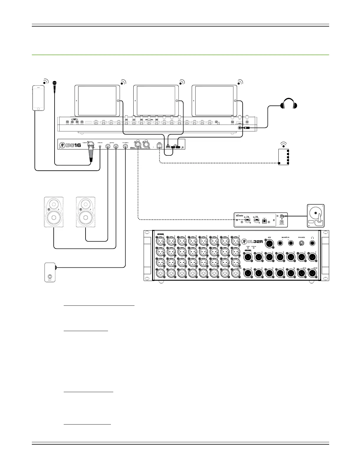
Appendix A : Hookup Diagram
Live Sound: House Engineer
Here’s a pretty common setup utilizing the full Axis system.
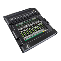
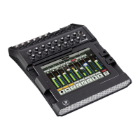
DC16 Front and Top Panels:
* Three iPads placed on the Smart Bridge.
* Pair of headphones connected to the phones jack.
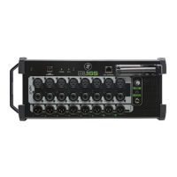
DC16 Rear Panel:
* Mic connected to the Talkback jack.
* Smart phone or MP3 player connected to the stereo input jack.
* Pair of XR-Series monitors connected to the L/R monitor jacks.
* One-button footswitch connected to the footswitch jack.
* Ethernet cable from the router to the Wi-Fi Control jack.
* Lightning cables from the Control and Charging jacks connected to the three iPads.
* Ethernet cable from the Dante jack on DC16 to the Dante jack on the DL32R.
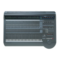
DL32R Front Panel:
* 1-24 XLR cables connected to inputs 1-24.
* 1-8 XLR or 1/4" cables connected to inputs 25-32.
* 1-14 XLR cables connected to outputs 1-14.
DL32R Rear Panel:
* Ethernet cable from the Dante jack on the DL32R to the Dante jack on DC16.
* Hard drive OR computer connected to one of the USB outputs.