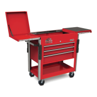
This document serves as an instruction manual for the MB199UC and MB199UCFD utility carts, along with their accessories, including the MB199UCSB and MB199UCSC models. It provides comprehensive guidance on the safe and effective use, assembly, and maintenance of these mobile storage units.
The primary function of these devices is to provide mobile storage for tools and other equipment, catering to various professional and personal needs. They are designed to be versatile, allowing for customization and expansion through a range of accessories.
Safety and General Usage:
Before assembling or using the utility cart, it is crucial to read all instructions provided in this manual to reduce the risk of injury. Users should always wear proper eye protection and protective gloves during assembly and use.
Key safety guidelines include:
- Drawer Management: Never open more than one loaded drawer at a time to prevent tipping.
- Weight Distribution: Avoid stepping in or on any drawer or available ledge.
- Mobility: Always close the lid and lock all drawers before moving the unit.
- Stationary Use: Apply the brake on all casters when the cart is left in a stationary position.
- Accessory Compatibility: Do not place or mount any apparatus on top of the unit that has not been specifically designed for the cart and approved for use. All approved accessories and attachments are listed in the accessories section of this manual.
- Component Integrity: Immediately replace damaged hinges or ball bearing slides with official manufacturer replacements.
- Drawer Installation: Improper installation of drawers and slides can lead to damage or injury. Ensure drawer stops are fully engaged and working correctly.
Maintenance Features:
The MB199UC class of carts is designed with several maintenance-free or low-maintenance features:
- Slides: The ball bearing slides come standard and do not require periodic lubrication, making them maintenance-free.
- Locking Mechanisms: Periodically apply prescribed lubrication to locks and lock mechanisms as needed. For key locks, graphite lock lubricant is recommended, while light grease or oil should be used for lock levers.
- Casters: The casters are maintenance-free, with no lubrication access on the swivel or wheel. The wheel features an oil-impregnated bushing that sits in a Delrin bushing, ensuring a long-lasting, smooth wear surface.
Drawer and Slide Management:
The manual provides detailed instructions for removing and installing drawers and their runners:
Removing a Drawer:
- Empty all contents from the drawer.
- Pull the drawer out to its full extended length.
- Locate the levers on the side of the drawer slides. Push down the lever on the right-hand slide and simultaneously pull up the lever on the left-hand slide.
- Pull the drawer out over the stops. The drawer can then be fully removed.
Installing a Drawer:
- Pull the slides out to their full extended position.
- Align the slides with the runners on the drawer and push the drawer in, keeping it level and even. Some force may be required over the last few inches to correctly realign the ball bearings.
Removing Drawer Runners and Slides:
- Remove the target drawer and the drawers immediately above and below it for better access to the slides.
- Pull the slides out to their full extended position.
- Wedge a flat-blade screwdriver under the top edge and lightly twist or pry to separate the slide frame from the box. Simultaneously lift the slide until it snaps out of position.
- Pull the slide forward and remove.
Installing Drawer Runners and Slides:
- Align the tab on the back edge of the slide with the square notch at the back edge of the slide support wall.
- Insert the forward tab on the slide into the slot on the cabinet slide support wall and push down until the slide snaps into position and is horizontal.
- Verify the position and firm connection of the slide before re-installing the drawer.
Removing Drawer Runners (from the drawer body):
- Locate the forward tab on the inside wall of the drawer body.
- With a slim object like a screwdriver, push in the protruding lower edge of the tab.
- While pushing in the tab, lift up on the drawer runner until it pops free and slide it forward.
Accessory Attachment and Relocation:
The MB199UC cart platform is designed to accept channeled corner rails, allowing for the attachment of a variety of accessories. This system enables users to create a custom configuration based on their needs.
Attaching or Removing Corner Rails:
- Remove the existing five fasteners from the locations on the cart.
- Place the large back wall of the corner rail against the cart and align the holes between the cart and rail. The rails should be oriented with the smaller channel facing outward towards either the front or back of the cart.
- Insert the topmost fastener and let the rail settle onto the fastener. Hold the rail in that settled position while fully tightening. This ensures the rail is not too high and does not interfere with the slide-out upper tray when opened.
- Proceed with inserting the other fasteners from the bottom up, ensuring all fasteners are fully tightened.
- To remove rails, reverse the order of operations, starting with the lowest fastener.
Attaching Corner Rail Caps:
After attaching the rails, side handle, bumpers, and accessories, install the corner rail caps.
- Place the corner rail cap on the top surface of the corner rail, aligning the cap holes with the holes on the corner rail.
- Secure the cap using flat head screws. Do not overtighten, as this may damage the rail cap. The holes in the corner rails are untapped, so the special thread-forming screws will cut their own thread.
Attaching and Relocating Side Handle and Bumpers:
The MB199UC utility cart platform accepts a height-adjustable side handle and bumpers, which attach using the same method as other accessories.
Side Handle Attachment:
- Insert the supplied wedge nut and button head fastener through the mounting holes on the handle bracket.
- Once the fastener is in the handle bracket, thread a small portion of the wedge nut onto the fastener, leaving enough slack to easily maneuver the assembly into the cart's corner rail slots.
- Attach all four threaded nut assemblies to both sides of the accessory before placing it in the slot of the corner rails.
- Once the threaded nuts are inserted in the slot on the corner rails, lower the handle into the desired position and fully tighten to prevent movement during use.
Bumper Attachment:
- Using the supplied hex nut and button head fastener, insert the fastener through the mounting holes on the bumper and partially thread on the nut, leaving plenty of slack.
- Once both fasteners and hex nuts are connected to the bumper, insert the hex nut into the smaller of the two tracks on the cart's corner rails. You may need to twist the hex nut to align it with the track.
- Once both nuts are inserted, slide the bumper into the desired height and tighten the fastener. Do not overtighten, as this may damage the bumper.
Attaching and Relocating General Accessories:
The MB199UC utility cart platform accepts a variety of specially designed accessories that attach via the corner rail system. This system allows for custom configuration.
- Insert the supplied wedge nut and button head fastener through the most outboard mounting hole on the accessory.
- Thread a small portion of the wedge nut onto the fastener, leaving enough slack to easily maneuver the assembly into the cart's corner rail slots.
- Attach threaded nut assemblies to both sides of the accessory before placing it in the slot of the corner rails.
- Once the threaded nuts are inserted in the slot on the corner rails, lower the accessory into the desired position and fully tighten to prevent movement during use.
- Accessory fasteners may need periodic tightening to prevent them from moving.
Lower Tray and Slide-Out Lower Tray:
The standard 3-drawer cart has a stationary lower tray that can be converted to accept a slide-out lower tray accessory.
- Remove the four sheet metal screws along the bottom flange of the tray wall and pull the tray wall up and out of the notches on either end of the side walls.
- Once these parts are removed, the slide-out lower tray accessory can be installed.
Slide-Out Lower Tray Usage:
- Safety Warning: The slide-out lower tray is for storage only and must never be used as a step.
- To prevent damage or injury, ensure the lower tray is in the closed position when moving the cart.
- The tray has stops that prevent it from extending completely, allowing it to hold up to 100 lbs.
- The lower tray handle/protective guards can be removed or repositioned using the set screws.
Locking System:
Locking Drawers:
- To lock the lower drawers, locate the lever arm on the back wall of the top compartment.
- Shift the lever to align with either the lock or unlock icon label in front of the lever. If no icons are present, shifting the lever to the right is unlocked, and to the left is locked.
Locking Cabinet and Top Compartment:
The MB199UC utilizes the same standard barrel lock as larger storage boxes.
- Ensure the serial number on the front face of the lock matches the serial number on the keys.
- The main barrel lock engages lock rods on the inside of the top compartment, which prevent the top slide-out trays from opening.
- To prevent the lock rods from sticking in the retracted position, apply a light-duty lubricant to the rods.
Side Box/Cabinet Attachment:
The MB199UC Utility Cart System allows for the easy attachment of the MB199UCSB or MB199UCSC side box or cabinet, utilizing existing hole patterns on the cart. These can be attached to either side of the cart.
- If the cart has corner rails already attached, they will need to be removed from the side where the side box/cab is to be installed.
- Attach the supplied casters to the outermost lower edge of the side box/cab.
- The side box/cab attaches using three of the holes for each vertical leg of the cart. If the topmost hole is number 1, holes 2, 3, and 4 will be used to mount the side box/cab to each corner.
- Remove the lower three drawers and open the top compartment lid of the side box/cab to access the mounting holes.
- Align the holes on the side box/cab with the holes on the main cart and use the supplied fasteners to finger-tighten all six fasteners to join the two main parts.
- Ensure the side box/cab is level and all casters are touching the floor before completely tightening the fasteners.
- If desired, accessory corner rails can be installed on the outside wall of the side box/cab.
Casters Attachment and Function:
Attaching Casters to Side Box or Side Cabinet:
Side boxes/cabs do not come with pre-installed casters.
- Select which side of the side box/cab will mount to the MB199UC. The casters will mount to the opposite side of the side box/cab.
- Locate the four mounting holes in each corner and align them with the supplied caster mounting plate.
- Insert all four fasteners and completely tighten.
Locking Casters:
The MB199UC utility cart has two different types of casters:
- Left Side Casters: These are 360-degree swivel casters that can be locked or made immobile by depressing the lock lever.
- Right Side Casters: These are 360-degree swivel casters that can be locked in the orientation of a fixed caster by depressing the lock lever. Note that this does not immobilize the wheel from spinning, only the caster from swiveling.
- The casters that come standard on the side box/cab are the 360-degree swivel casters, which can be locked or made immobile by depressing the lock lever.
This comprehensive manual ensures that users can safely and effectively assemble, operate, and maintain their Mac Tools utility carts and accessories, maximizing their lifespan and utility.