INSTALLATION INSTRUCTIONS
FOR R.V. RANGES 16, 18 & 22 SERIES
IMPORTANT - "THIS PRODUCT IS NOT APPROVED FOR MARINE USE."
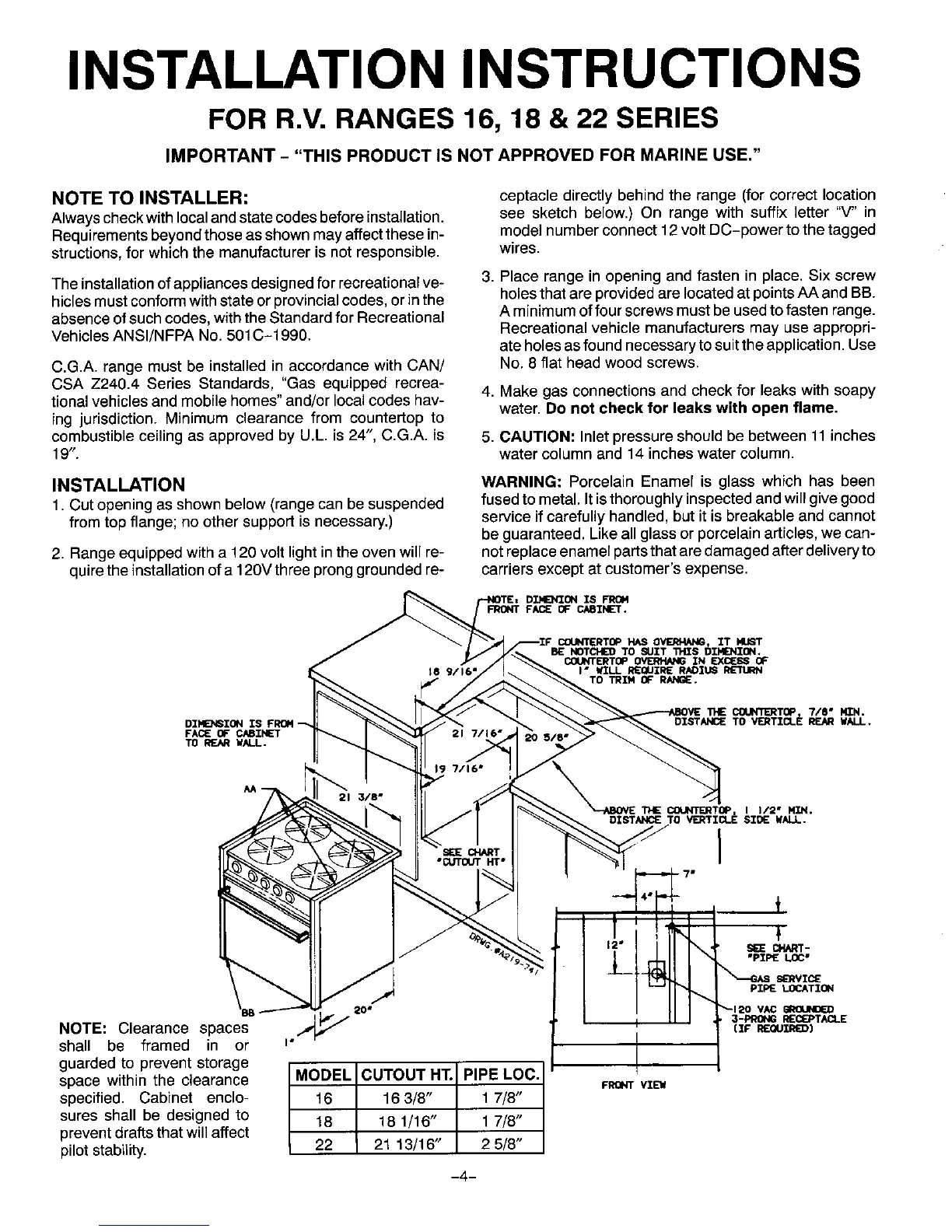
NOTE TO INSTALLER: ceptacle directly behind the range (forcorrect location
Alwayscheckwithlocalandstatecodesbeforeinstallation, see sketch below.) On range with suffix letter "V" in
Requirementsbeyondthoseas shownmayaffectthese in- modelnumberconnect12 voltDC-power tothetagged
structions,forwhichthe manufactureris notresponsible, wires.
Theinstallationofappliancesdesignedfor recreationalve- 3. Place range in openingand fasten in place.Six screw
hiclesmustconformwithstateorprovincialcodes,orinthe holesthat areprovidedare locatedatpointsAA andBB.
absenceofsuchcodes,withtheStandardforRecreational A minimumoffourscrewsmustbeusedto fasten range.
VehiclesANSI/NFPA No.501C-1990. Recreationalvehiclemanufacturersmay use appropri-
ate holesasfoundnecessarytosuittheapplication.Use
C.G.A. range must be installedin accordancewith CAN/ No. 8 flat head woodscrews.
CSA Z240.4 Series Standards, "Gas equippedrecrea-
tionalvehiclesandmobilehomes"and/orlocalcodeshav- 4. Make gas connectionsand checkfor leakswithsoapy
water.Do not check for leaks with open flame.
ing jurisdiction.Minimum clearance from countertopto
combustibleceilingas approvedby U.L. is 24", C.G.A. is 5. CAUTION: Inletpressureshouldbe between11 inches
19". watercolumnand 14 incheswatercolumn.
INSTALLATION WARNING: Porcelain Enamel is glass which has been
1.Cutopeningasshownbelow(rangecan be suspended fusedtometal.Itisthoroughlyinspectedandwillgivegood
from topflange;no othersupportis necessary.) serviceifcarefullyhandled,butit is breakableand cannot
be guaranteed.Likeallglassorporcelainarticles,wecan-
2. Rangeequippedwith a 120 volt light in the oven will re- not replaceenamel partsthat aredamaged after deliveryto
quire the installation of a 120Vthree prong groundedre- carriers except at customer's expense.
1HE COIJNTE_TOP 7/8" N,TN.
DZSTANCE TO VE_TZCL_ REAR WALL.
I
12m
20 # _-120 VAC GROUNDED
NOTE: Clearance spaces _ tz_ Eouz_)
shall be framed in or ="
guarded to prevent storage
space within the clearance MODEL CUTOUTnT.j"/ PIPE LOC._/ FRONTVZEU
specified. Cabinet enclo- 16 _/ 17/8" /
sures shall be designed to 18 18 1/16 / 17/8" I
prevent draftsthat will affect
/ /
pilotstability. 22 21 13/16" / 2 5/8" /
-4-