INSTALLATION INSTRUCTIONS
FOR R.V. COOKTOP 85 SERIES
IMPORTANT - "THIS PRODUCT IS NOT APPROVED FOR MARINE USE."
NOTE TO INSTALLER: 2. Align the 3/8" gas supply line with the hole provided in
Always checkwith localandstate codesbefore installation, burner box so it will slide into place when the range is
Requirements beyondthoseas shown mayaffectthese in- placed into the opening.
structions, for which the manufacturer is not responsible. 3. Place the range in position and fasten down with four
wood screws through holes provided in the side trim Io-
The installation of appliances designedfor recreational ve- cated at point "A" in the diagram below.
hiclesmustconform with state orprovincial codes, or inthe 4. Connect gas supply line.
absence of such codes,withthe Standardfor Recreational
Vehicles ANSI/NFPA No. 501C-1990. 5. Checkall gas connectionsfor leakswith soap andwater
solution. Do not use open flames for checking gas
leaks.
C.G.A. range must be installed in accordance with CAN/
CSA Z240.4 Series Standards, "Gas equipped recrea- 6. CAUTION: Inlet pressure should be between 11 inches
tional vehicles and mobile homes"and/or localcodes hav- water column and 14 inches water column.
ing jurisdiction. Minimum clearance from countertop to
combustible ceiling as approved by U.L. is 24"" C.G.A. is WARNING: Porcelain Enamel is glass which has been
19". fusedto metal.It isthoroughly inspectedand will give good
service if carefully handled, but it isbreakable and cannot
be guaranteed. Like all glass or porcelain articles,we can-
INSTALLATION not replaceenamel partsthat aredamaged afterdeliveryto
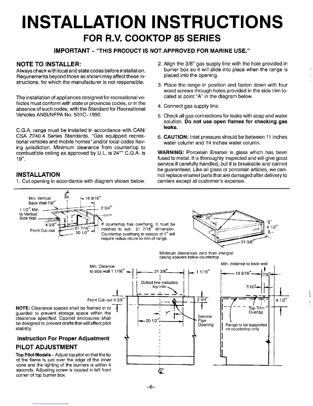
1. Cut opening in accordance with diagram shown below, carriers except at customer's expense.
Min. Vertical _ _ 189/16"
BackWall 7/8" ! I _ ,,
to Vertical _ _,, _
TI I'h--" IJ
4 3/8"-_}---J._,__ If countertop has overhang, it must be
FrontCut-out ___._-217/16/;_ notched to suit 21 7/16" dimension. _.._._l_ _ j_ /2"
20 1/2 . t_ . _ ]-_.J 7 _,.
_ j],_.__ 20 1/2" --_ Countertop overhang in excess of 1 will P
require radius return totrim of range.
Minimum clearances zero from intergral
casing spacers below countertop.
Min. Distance Min.distance to back wall
to side wall 1 1/16" _.- _. 21 3/8" 1 1/16" _ 189/16 _7/8 ---
i
!
Dotted line indicates
_t_ t,.m
Front Cut-out 43/8" 23_" 41/2"
, T
NOTE: Clearance spaces shall be framed in or T "__ : T - Overl2p
guarded to prevent storage space within the -_-, 7" Service
clearance specified. Cabinet enclosures shall 2o 1/2". "_'_-Pipe
be designed to prevent drafts that will affect pilot Opening Range to be supporte<
stability, on countertop only
Instruction For Proper Adjustment
PILOT ADJUSTMENT
Top Pilot Models - Adjust top pilotsothat the tip
o_the _lame is just over the edge of the inner i
cone and the lighting of the burners is within 4 '
seconds. Adjusting screw is located in left front __.
corner of top burner box.
-6-