Page 8 of 19 507388-03Issue 2110
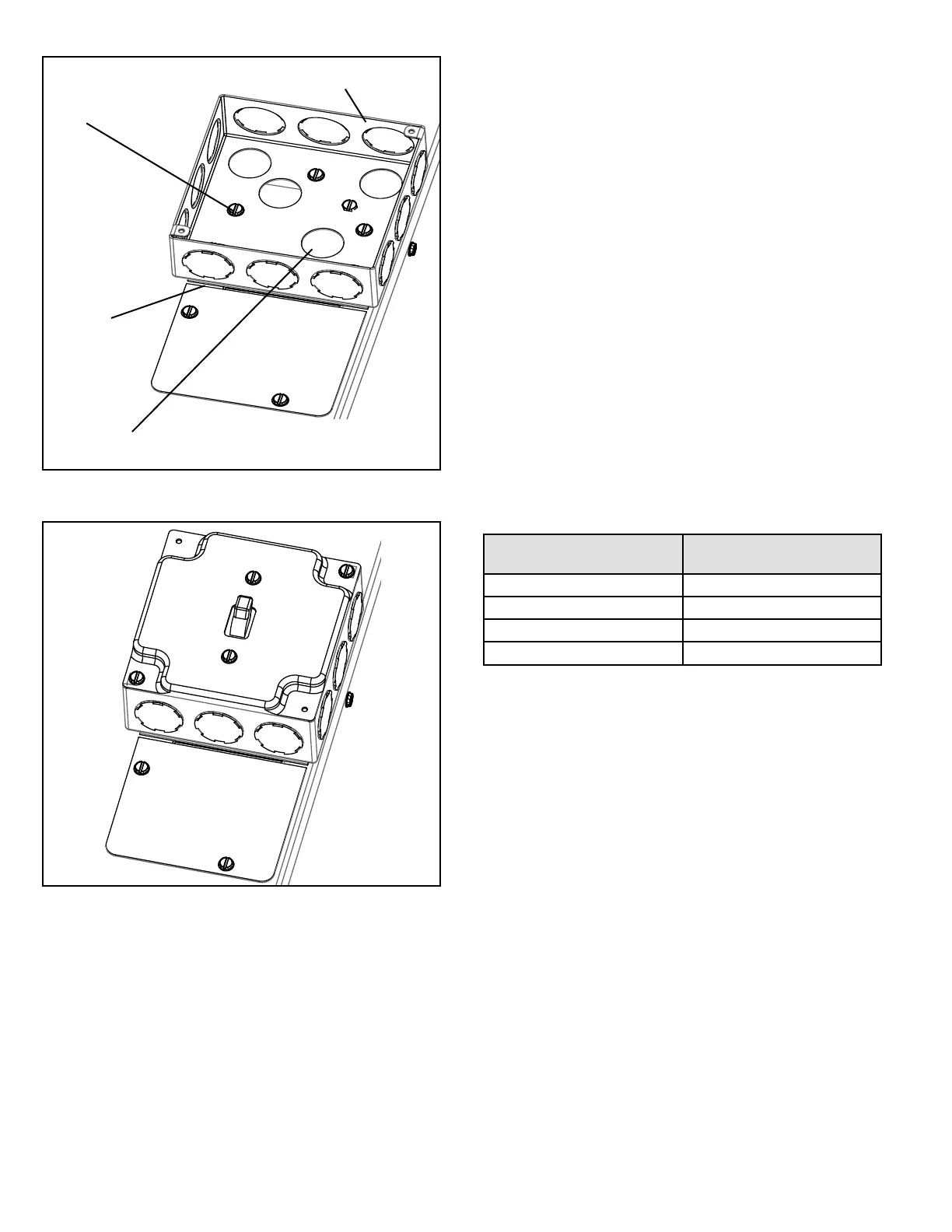
Junction Box
Use Screws to secure
Junction box
No Gap
Remove Knock-out over opening, pull unit wiring leads through
Figure 5.
Figure 6.
Thermostat
Install the thermostat according to the directions furnished
with it. The thermostat must be located on an inside wall
where it will not be aected by drafts, sunlight, or any other
heat producing appliances. Connect the thermostat wires
to the low voltage leads on top of the unit following the
wiring diagram attached to the unit. The heat anticipator
setting is 0.50 amp.
NOTE: For HWC8*30 models, a two-stage thermostat is
recommended for reaching highest eciency and full use
of two-stage compressor.
Air Filter
All indoor return air must be ltered. A permanent-type
lter is furnished with the unit, located directly behind the
access panel. Removing the panel permits access to the
lter. See Figure 3.
If an installation is made in which it is more desirable to
mount the lter exterior to the unit, in the return duct work
or elsewhere, the permanent lter can be used or replaced
with a disposable lter. If a disposable lter is used, refer
to the information provided in Table 1 when sizing the
disposable lter.
Model Number
Filter Area
(sq. in.)
HWC8*12 300
HWC8*18 480
HWC8*24 480
HWC8*30 480
Table 1. Minimum Required Surface Area for
Disposable Filters
Supply and Return Duct(s)
Provide duct(s) sized suciently to handle the larger of the
air volumes for heating or cooling provided by this model.
Connect the supply duct to the top of the unit using canvas
connections or other exible connections to prevent noise
transmission into the duct system.
To connect the return duct to the system, use a straight
piece of duct 22” wide by 6” deep. Insert the duct into the
return opening in the bottom of the unit and ange the
duct over the existing anges around the opening inside
the unit. Make sure that all sides of the duct are anged
over to permit removal of the cooling chassis if required.
Use a exible connection to attach the remainder of the
return duct. The return duct should be sealed to the unit
casing and must terminate outside the space containing
the furnace.