3. Zero probe fails to set the display to zero: Check if the Relative function is switched off.
Make sure, that the probe is apart from larger magnetic fields (AC and DC) during zeroing
and that it is not moved. Use the shielding chamber. If the display still can not be set to zero,
probably the Hall sensor in the probe is defective. You may send it to MAGNET-PHYSIK
for inspection.
A Hall sensor may be damaged by mechanical stress, as it can occur if the probe stem is bent.
Strokes or excessive temperatures can also cause damage.
8.5 Connectors
8.5.1 Probe Connector
The DB 15 connector on the front panel is used for probe connection. The plug of the probe
must carefully be inserted to avoid bending of the contact pins. Use the two screws to fix the
plug.
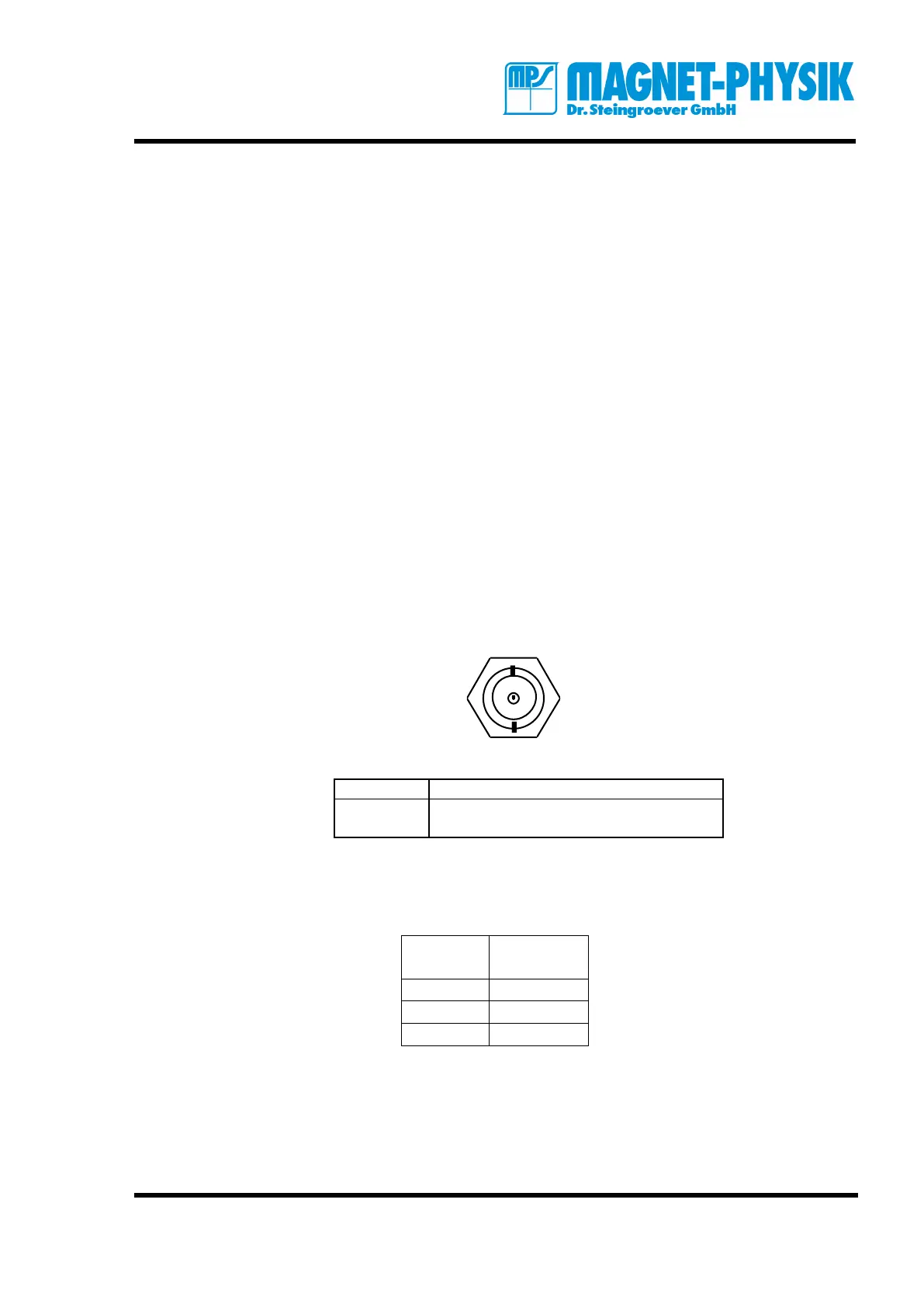
8.5.2 Analog Output
The analog output can be accessed via the BNC (Bayonet Nut Connector). The signal is on the
center contact. The analog output gives a 3 V signal, that is proportional to the output voltage of
the sensor. It is not corrected for linearity and offset and will therefore differ from die value
shown in the display.
8.5.3 Serial Interface RS 232
The 9-pole connector for the serial interface is located on the rear panel. A standard null-
modem cable can be used.
Communication parameters:
Baud rate 4800, 9600, 19200 (selectable)
Data bits 8
Stop bit 1
Parity bit none