IMPULSE®•G+ & VG+ Series 3 to Series 4 Transition Guide August 2011
Page 9 of 54
Magnetek, Inc.
Product Transition Guide
IMPULSE
®
•G+ & VG+ Series 4
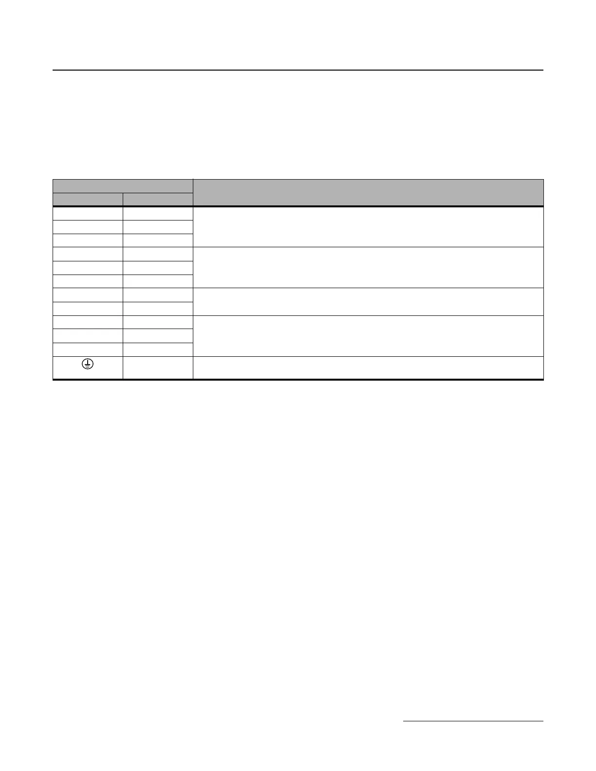
1.5 Terminals
Main Circuit Terminals
As G+ Series 3 and G+ Series 4 drive models may have different terminal sizes (depending on capacity),
the terminal must be carefully checked before replacement.
The main terminal functionality has not been changed between the G+ Series 3 and the G+ Series 4.
Main Terminals
Note
G+ Series 3 G+ Series 4
R/L1 R/L1
Main circuit power supply input, connects line power to the driveS/L2 S/L2
T/L3 T/L3
U/T1 U/T1
Drive Output, connects to the motorV/T2 V/T2
W/T3 W/T3
B1 B1
Braking resistor
B2 B2
+2 +2
DC reactor connection (+1, +2) (remove shorting bar)
DC power supply input (+1, -)
Braking unit connection (+3, -)
+1 +1
—+3
— Ground Terminal (10Ω or less)
 Loading...


