Product Transition Guide
IMPULSE
®
•G+ & VG+ Series 4
IMPULSE®•G+ & VG+ Series 3 to Series 4 Transition Guide August 2011
Page 32 of 54
Magnetek, Inc.
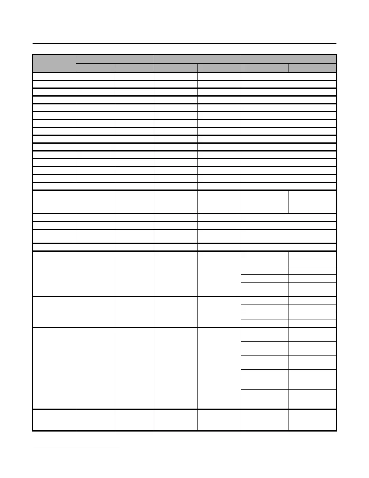
Reference 3 B1-03 60.00 Hz B1-03 60.00 Hz --
Reference 4 B1-04 0.00 Hz B1-04 0.00 Hz --
Reference 5 B1-05 0.00 Hz B1-05 0.00 Hz --
Reference 6 B1-06 0.00 Hz B1-06 0.00 Hz --
Reference 7 B1-07 0.00 Hz B1-07 0.00 Hz --
Reference 8 B1-08 0.00 Hz B1-08 0.00 Hz --
Reference 9 B1-09 0.00 Hz B1-09 0.00 Hz --
Reference 10 B1-10 0.00 Hz B1-10 0.00 Hz --
Reference 11 B1-11 0.00 Hz B1-11 0.00 Hz --
Reference 12 B1-12 0.00 Hz B1-12 0.00 Hz --
Reference 13 B1-13 0.00 Hz B1-13 0.00 Hz --
Reference 14 B1-14 0.00 Hz B1-14 0.00 Hz --
Reference 15 B1-15 0.00 Hz B1-15 0.00 Hz --
Reference 16 B1-16 0.00 Hz B1-16 0.00 Hz --
Jog Reference B1-17 6 Hz B1-17 6.00 Hz --
Ref Priority B1-18 0 B1-18 0
0: Digital Ref Only 0: Digital Ref Only
1: Analog Ref Only 1: Analog Ref Only
2; Higher Ref Sel 2: Higher Ref Sel
Ref Upper Limit B2-01 100.0% B2-01 100.0% --
Ref Lower Limit B2-02 2.0% B2-02 0.0% --
Ref 1 Lower Limit B2-03
G+: 2.0%
VG+: 0.0%
B2-03
G+: 2.0%
VG+: 0.0%*
*Initial value set by X-Press programming.
Alt Upper Limit B2-04 100.0% B2-04 0.0% --
Reference Source B3-01 1 B3-01 1
0: Operator 0: Operator
1: Terminals 1: Terminals
2: Serial Com 2: Communication
3: Option PCB 3: Option PCB
4: Pulse Input (H6-
01)
4: Pulse Input (H6-
01)
Run Source B3-02 1 B3-02 1
0: Operator 0: Operator
1: Terminals 1: Terminals
2: Communication 2: Communication
3: Option PCB 3: Option PCB
Stop Method B3-03
G+: 1
VG+: 6
B3-03
G+: 1
VG+: 6
0: Decel to Stop
(A1-03=0)
0: Decel to Stop
1: Coast to Stop
(A1-03=1)
1: Coast to Stop
2: DC Injection to
Stop (G+ only)
--
4: Decel with timer
(Traverse mode
only)
4: Decel with timer
(Traverse mode
only)
6: No Load Brake
(A1-03=2) (VG+
only)
6: No Load Brake
(See No-Load
Brake Start/Stop)
Reverse Oper B3-04 0 B3-04 0
0: Normal Rotation 0: Standard
1: Exchange
Phases
1: SwitchPhase
Order
Parameter
Name
Series 3 Series 4 Comments
No. Default No. Default Series 3 Series 4
 Loading...


