Do you have a question about the Magnetek Impulse G+ series 4 and is the answer not in the manual?
Step-by-step procedure for installing the IMPULSE®•G+ & VG+ Series 4 drive.
Essential practices for properly wiring the drive to ensure safe and reliable operation.
Step-by-step instructions for wiring the main power circuit of the drive.
Description of the Safe Torque Off function for mechanical maintenance and E-stops.
Procedures for wiring the encoder circuit for speed and shaft position feedback.
Utilizing the automatic tuning function to adapt the inverter to various motors.
Step-by-step procedure for rotational auto-tuning on an unloaded motor.
Procedure for auto-tuning without decoupling the motor, requiring short crane movement.
Overview of various special functions available for enhanced drive operation.
Load-limiting feature to prevent lifting overweight loads.
Procedure to set up Load Check II by measuring current/torque at different zones.
Features for increased productivity by allowing faster movement with light loads.
Dynamically controls motor torque output, limiting torque in Open and Closed loop vector control.
Hoist NLB feature in Flux Vector control to minimize structure fatigue.
Start and stop sequence designed specifically for No Load Brake Hoists.
Function to operate the drive during encoder-related faults.
Weight Calculation function for hoisting applications based on motor torque.
General guide for investigating and correcting drive issues.
List of drive faults and alarms with descriptions and corrective actions.
Specific guidance for diagnosing and resolving faults related to the encoder feedback system.
Describes speed deviation faults and their corrective actions, often related to encoder issues.
Identifies problems with encoder feedback signals, including wiring and alignment.
Output current exceeds inverter rated output current, possibly due to shorts or parameter issues.
Procedures for checking the power section of the drive when power is off.
| Output Frequency | 0 - 400 Hz |
|---|---|
| Humidity | 5% to 95% non-condensing |
| Dimensions | Varies by model |
| Weight | Varies by model |
| Enclosure | NEMA 1, NEMA 12, NEMA 4 |
| Communication | Profibus |
| Output Current | Varies by model |
| Control Method | Closed Loop Vector Control |
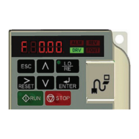
| Display | LCD |
| Protection Features | Overcurrent, Overvoltage, Undervoltage, Short Circuit |
| Operating Temperature | -10°C to 50°C |
| Storage Temperature | -20°C to 60°C (-4°F to 140°F) |