IMPULSE®•G+ & VG+ Series 4 Instruction Manual – February 2017
5-7
Stop Method
B03-03 selects the stopping method suitable for the particular application.
Table 5-5: Stop Method Parameter Settings
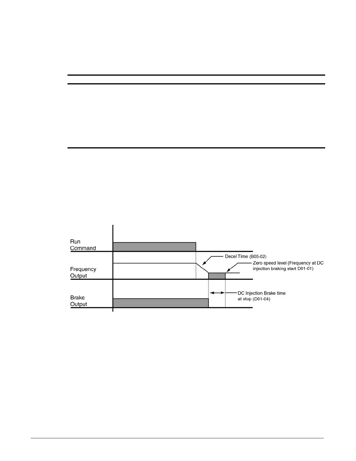
Decel to Stop (B03-03=0)
Upon removal of the FWD or REV run command, the motor decelerates at a rate determined by the
time set in deceleration time 1 (B05-02) and DC injection braking is applied after the DC injection
start frequency D01-01 has been reached. If the deceleration time is set too short or the load inertia
is too large, an overvoltage fault (OV) or deviation (DEV) may occur during deceleration. In this case,
increase the deceleration time or install an optional braking transistor and/or braking resistor.
Figure 5-2: Decel to Stop
Parameter Display Function Range Default Model
B03-03 Stopping Method Determines stop method. 0, 1, 4, 6 G+: 0*
VG+: 6*
0 Decel to Stop (Fig 5-2) G+/VG+
1 Coast to Stop (Fig 5-3) G+/VG+
4 Decel with timer
(Traverse mode
only)
(Fig 5-4) G+/VG+
6 No Load Brake See No-Load Brake Parameter
Group C8.
VG+
* Initial value is determined by X-Press Programming (Table 4-6, 4-7, or 4-8 on pages 4-12, 4-13, and 4-14).

 Loading...


