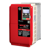
IMPULSE®•G+ & VG+ Series 4 Instruction Manual - February 2017
1-8
AC Reactor Specifications
Reactors, both as input (line) and output (load) devices, protect adjustable frequency drives, motors,
and other load devices against excessive voltage and current.
The following guidelines may help determine input and output reactor requirements:
• The following tables are only a guideline. The motor FLA should not exceed the reactor FLA.
• Install an input reactor if the power source is greater than 500 kVA.
• Install an output reactor if the distance between the drive and the motor exceeds 150 feet.
• Install an output reactor if a device, such as a power limit switch, is used to disconnect the motor
from the drive. Use a power limit switch early break circuit to fault the drive.
• Install one output reactor per drive for a multiple-drive arrangement requiring reactor protection.
• For a multiple drive arrangement, an input reactor for each drive is recommended for optimal
protection. However, if the drives are within two drive sizes of each other, a single input reactor
can be used. The reactor must be rated at amperage equal to or greater than the sum of the
amperage for all the drives.
• Reactors are most effective when the reactor current rating approaches the drive current rating.
Heatsink overtemperature Thermostat trips at 105°C (221°F)
Torque limit selection Separate functions for FORWARD, REVERSE, REGEN; all selectable from
0–300%
Stall prevention Separate functions for accel, decel, at-speed, and constant horsepower
region
Other protection features VG+: Speed deviation, overspeed, mechanical brake failure, lost output
phase, failed-oscillator, PG-disconnect, roll-back detection, micro controller
watchdog, internal braking transistor failure, torque output limit, motor
overcurrent, inverter overcurrent, input phase loss.
G+: Lost output phase, micro-controller watchdog, internal braking resistor
failure, motor overcurrent, inverter overcurrent, input phase loss.
DC bus voltage indication Charge LED is on until DC bus voltage drops below 50 VDC
Location Indoors; requires protection from moisture, corrosive gases, and liquids
Ambient operating temperature -10° to 60°C (14° to 140°F)*
-10° to 65°C (14° to 149°F)**
Storage temperature -20°C to +70°C (-4°F to 158°F)
Humidity 95% relative humidity or less and free of condensation
Vibration
10 to 20 Hz at 9.8 m/s
2
20 to 55 Hz at 5.9 m/s
2
(Models 2003 to 2180, 4001 to 4150, and 5001 to
5077) or
20 to 55 Hz at 2.0 m/s
2
(Models 2215 to 2415, 4180 to 4605, and 5099 to
5200)
Elevation 1000 m or lower, up to 3000 m with derating.
Orientation Install the drive vertically to maintain maximum cooling effects.
Specification Specification Value and Information for All Models
* 2kHz carrier frequency
** Maximum rated temperature of 65°C at the drive chassis with factory approved air handling system

 Loading...