IMPULSE®•G+ & VG+ Series 4 Instruction Manual - February 2017
3-18
Table 3-5: Terminal and Wire Specifications
Dip Switches
DIP Switches are described in this section. The functions of the DIP switches are shown in the table
below.
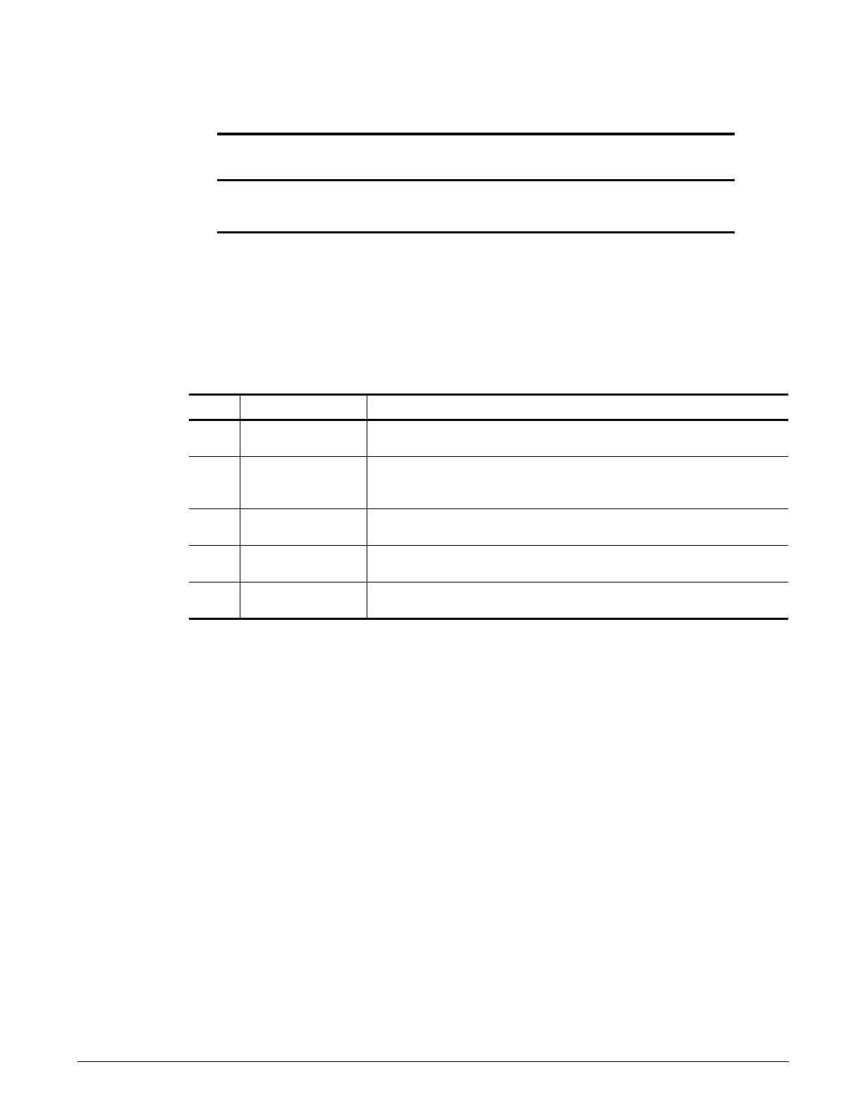
Table 3-6: DIP Switches
Terminal
Symbol
Terminal
Screw
Clamping Torque
Lb-in (N-m)
Wire Range
AWG (mm
2
)
TB M3
4.2 to 5.3
(0.5 to 0.6)
26 to 16
(Stranded: 0.14 to 1.5)
(Solid: 0.14 to 1.5)
Name Function Setting
S1
Input method for
analog input A2
V: 0 to 10 VDC or -10 to 10 VDC (internal resistance: 20 ) (default)
I: 4-20mA (internal resistance: 250 )
S2
RS-485 and RS-422
terminating
resistance
OFF: No terminating resistance (default)
ON: Terminating resistance of 120
S3
Hardware Base
Block Configuration
See page 3-19 for setting details
S4
Analog 3/PTC input
select
AI: A3 is used as Analog Input 3 (default)
PTC: A3 is used with a Positive Temperature Coefficient (PTC) thermistor
S5
Output method for
analog output FM
V: 0 to 10 VDC or -10 VDC to 10 VDC (default)
I: 4 to 20 mA

 Loading...


