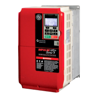
IMPULSE®•G+ & VG+ Series 4 Instruction Manual - February 2017
1-5
Introduction
Assessing the System Requirements
It is important to know how the drive will be utilized before working on installation and wiring. Please
know the requirements for the following components:
• Speed control method(s) - i.e. stepped, stepless, infinitely variable
• Braking method(s) - coast to stop, decel to stop, No Load Brake (NLB) Hoist
• Power source voltage, number of phases, and kVA rating
• Power source location
•Wire size
• Grounding location and method
• Control wiring sources - i.e. cab, pendant, radio
Assessing the Drive Environment
When choosing a location for IMPULSE
®
•G+ & VG+ Series 4, perform the following steps:
1. Ensure that a three-phase 200 to 240 VAC 50/60 Hz power supply is available for a 230 VAC-
rated drive, a three-phase 380 to 480 VAC 50/60 Hz power supply is available for a 460 VAC-
rated drive, and a 500 to 600 VAC 50/60 Hz power supply is available for a 575 VAC-rated drive.
2. Ensure the encoder is supplied with +5 VDC or 12 VDC.
3. If the RMS encoder current requirement is greater than 200 mA, provide an auxiliary power
supply to the encoder.
4. Ensure that the drive-to-motor wiring distance is less than 150 ft. unless appropriate reactors,
filters, and/or inverter duty motor is used.
5. Ensure that the drive circuit wiring is protected or isolated from:
• Ambient temperatures outside the range of +14°F to +140°F (-10°C to +60°C) at 2 kHz
carrier frequency.
• Rain or moisture
• Corrosive gases or liquids
• Direct sunlight
• Severe mechanical vibration
6. Ensure that the drive is housed in an appropriate NEMA-rated enclosure.
7. For severe-duty applications (long lifts, for example) or with 75-HP-or-greater motors, ensure
that the drive control system (including dynamic braking resistors) is adequately cooled, even
though the ambient temperature limit is not exceeded. For more information, contact Magnetek.

 Loading...