4
48-651 SIL Certified Safety Manual for E3 Modulevel
®
1.3 Determining Safety Integrity Level (SIL)
Safety Instrumented System designers using the
E3 MODULEVEL must verify their design per applicable
standards.
Three limits must be met to achieve a given SIL level:
1. The PFD
AVG
numbers for the entire Safety Instrumented
Function (SIF) must be calculated. Table 2 shows the rela-
tionship between the Safety Integrity Level (SIL) and the
Probability of Failure on Demand Average (PFD
AVG
).
2. Architecture constraints must be met for each subsystem.
Table 3 can be used to determine the achievable SIL as a
function of the Hardware Fault Tolerance (HFT) and the
Safe Failure Fraction (SFF) for each subsystem in a safety
system (Type B–complex components as per IEC 61508
Part 2) of which the level transmitter is just one component.
3. All products chosen for use in the SIF must meet the
requirements of IEC 61508 for the given SIL Capability
level or be justified based on proven in use data collected for
each job.
The exSILentia tool from exida is recommended for design
verification. This automatically checks all three limits and
displays the results for any given design. The E3 MOD-
ULEVEL is in the exSILentia database. This tool contains
all needed failure rate, failure mode, SIL Capability and
common cause data as well as suggested proof test methods.
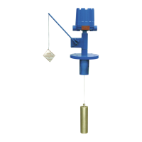
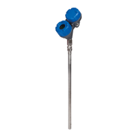
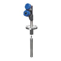
2.0 Applicable Models
This manual is only applicable to the HART versions of
the E3 MODULEVEL transmitter shown in Table 1.
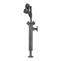
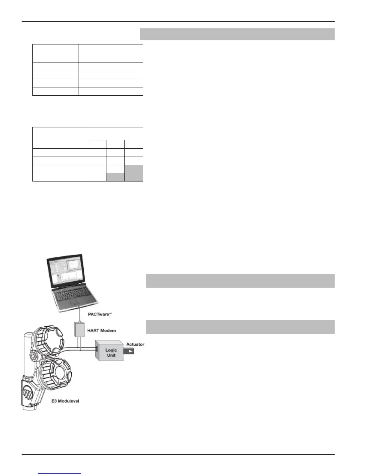
3.0 Level Measuring System
The diagram at left shows the structure of a typical measuring
system incorporating the E3 MODULEVEL transmitter.
This SIL 2/3 Certified device is only available with an ana-
log signal (4–20 mA) with HART communications; and,
the measurement signal used by the logic solver can be the
analog 4–20 mA signal proportional to the Level, Interface
Level or Density.
• For fault monitoring, the logic unit must recognize both
high alarms (≥ 21.5 mA) and low alarms (≤ 3.6 mA).
• If the logic solver loop uses intrinsic safety barriers, caution
must be taken to ensure the loop continues to operate
properly under the low alarm condition.
Figure 1
Typical System
Table 3
Minimum hardware fault tolerance
Type B sensors, final elements and non-PE logic solvers
SFF
Hardware Fault
Tolerance (HFT)
0 1 2
None: <60%
N
ot
Allowed
SIL 1 SIL 2
Low: 60% to <90% SIL 1 SIL 2 SIL 3
Medium: 90% to <99% SIL 2 SIL 3
High: ≥99% SIL 3
Table 2
S
IL vs. PFDavg
Safety
Integrity Level
(SIL)
Target Average
probability of failure
on demand (PFDavg)
4 ≥10
-5
to <10
-4
3 ≥10
-4
to <10
-3
2 ≥10
-3
to <10
-2
1 ≥10
-2
to <10
-1
 Loading...