Do you have a question about the Magnetrol A10 and is the answer not in the manual?
Read manual before installing; includes safety messages and explosion hazards.
Details the five-year warranty terms and conditions for controls.
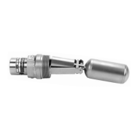
Explains the magnetic attraction principle of displacer switch operation.
Details the sequence of operation based on liquid level changes.
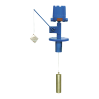
Covers floating roof detection and Proof-er control operation.
Instructions for unpacking, inspecting for damage, and recording serial numbers.
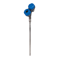
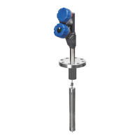
Guidance on properly mounting the displacer unit in the tank or vessel.
Instructions for conduit positioning and terminal block wiring.
Provides diagrams for single, dual, and triple stage DPDT and SPDT contacts.
General advice on keeping the control clean and functional.
Details monthly checks for wear, misalignment, and insulation.
Lists actions to avoid, like leaving covers off or using jumpers.
Guides on identifying and resolving operational issues in the control.
Specific steps to diagnose issues with the switch mechanism itself.
Procedures to test the control's overall performance and sense unit.
Troubleshooting steps for the Proof-er function.
Details FM, CSA, ATEX, and CE approvals and classes.
Lists basic electrical ratings for different switch series.
Details pressure and temperature ratings for various models.
Provides dimensional data and actuating levels for Model A10.
Provides dimensional data and actuating levels for Model A15.
Details the outline dimensions for Model B10 with different arrangements.
Provides actuating levels based on specific gravity and temperature.
Details the outline dimensions for Model B15.
Lists actuating levels based on specific gravity and temperature.
Details the outline dimensions for Model C10 with different arrangements.
Provides actuating levels based on specific gravity and arrangements.
Details the outline dimensions for Model C15.
Provides actuating levels based on specific gravity and temperature.
Lists dimensional data for Proof-er components.
Lists part numbers for Proof-er handle, spring, cable, etc.
Lists part numbers for enclosing tubes, gaskets, springs, body bushings, and flanges.
Provides part numbers for displacers made of Porcelain, Stainless Steel, and Brass.
Explains part number codes and specific gravity limits for A10/A15.
Lists codes for switch mechanisms and NEMA enclosures for A10/A15.
Explains part number codes and specific gravity limits for B10/B15.
Lists codes for switch mechanisms and NEMA enclosures for B10/B15.
Explains part number codes and specific gravity limits for C10/C15.
Lists codes for switch mechanisms and NEMA enclosures for C10/C15.
Details the RMA process, required information, and cleaning standards.
| Technology | Displacer |
|---|---|
| Measuring Principle | Buoyancy |
| Service | Liquid level measurement |
| Mounting | Top mount, side mount |
| Output | Pneumatic |
| Pneumatic Output | 3-15 psi (0.2-1.0 bar) |
| Pneumatic Supply Pressure | 20 psig (1.4 bar) |
| Process Connection | Flanged, threaded |
| Enclosure Rating | NEMA 4X, IP66 |
| Material | 316 stainless steel |