EasyManua.ls Logo

Magnetrol E3 Modulevel User Manual

Magnetrol E3 Modulevel
36 pages
To Next Page IconTo Next Page
Page #1 background imageLoading...
Page #1 background image
Liquid Level
Displacer Transmitter
Installation and Operating Manual
®
E3 Modulevel
®
Question and Answer IconNeed help?

Do you have a question about the Magnetrol E3 Modulevel and is the answer not in the manual?

Magnetrol E3 Modulevel Specifications

General IconGeneral
BrandMagnetrol
ModelE3 Modulevel
CategoryMeasuring Instruments
LanguageEnglish

Summary

Installation and Operating Manual

E3 Modulevel Transmitter Overview

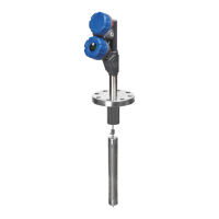
Introduction to the Liquid Level Displacer Transmitter.

Principle of Operation

Level Measurement Mechanism

How liquid level changes are detected via LVDT.

Interface and Density Tracking

Capabilities for measuring interface levels and fluid density.

Mounting Procedures

Wiring and Connections

Electrical Safety Precautions

Cautionary notes regarding power and grounding.

Grounding and Shielding Practices

Proper methods for grounding shield wires.

Intrinsically Safe and Explosion Proof Wiring

Requirements for hazardous area wiring and barriers.

Configuration and Setup

Password Protection Features

Setting up and managing password security for configuration.

Level Measurement Configuration

Setting Level Parameters

Configuring level units, specific gravity, temperature, and span points.

Level Measurement Configuration (Continued)

HART Communication Configuration

Setting HART poll address, loop mode, and trim values.

Loop Test and Value Capture

Performing loop tests and capturing 4mA/20mA points.

Interface Measurement Configuration

Interface Calibration Overview

Factory settings; user enters operating temperature, wet calibration.

Configuring Interface Parameters

Setting level units, temperature, span points, offset, and damping.

Interface Measurement Configuration (Continued)

HART Configuration for Interface

Setting HART poll address, loop mode, and trim for interface.

Loop Test and Capture for Interface

Performing loop tests and capturing interface span points.

Density Control Configuration

Density Calibration Overview

Factory calibrated; user enters operating temperature for density.

Configuring Density Parameters

Setting operating temperature, span points, and damping for density.

Density Control Configuration (Continued)

HART Configuration for Density

Setting HART poll address, loop mode, and trim for density.

Capturing Density Span Points

Setting 4mA for min S.G. and 20mA for max S.G.

Wet Calibration Guidelines

Level Measurement Calibration Steps

Procedure for calibrating 4mA/0% and 20mA/100% levels.

Interface Measurement Calibration Steps

Procedure for calibrating interface levels with displacer immersion.

Wet Calibration Guidelines (Continued)

Interface Calibration with Water

Calibrating interface using water with specific gravity examples.

Interface Calibration with Different Liquids

Using liquids with varying specific gravities for interface calibration.

Advanced Configuration and Diagnostics

Accessing Diagnostic Screens

Reviewing factory parameters, diagnostic messages, and runtime.

Advanced Calibration Submenu

User Calibration Procedure Details

Steps for matching electronics or replacing parts with user calibration.

Capturing Calibration Points (4mA/20mA)

Detailed steps for capturing low and high calibration values.

PACTware ™ Configuration Tool

Configuration Using HART ® Communication

HART ® Configuration Menu Structure

Maintenance and Troubleshooting

Troubleshooting Common Problems

Guide to diagnosing and resolving system issues based on symptoms.

Maintenance and Diagnostics

Error Message Interpretation

Troubleshooting Error Messages

Diagnosing and resolving 'SecFltHi', 'CoreDrop', 'PriFault' errors.

Maintenance and Part Replacement

Transmitter Head Removal and Installation

Procedure for safely removing and replacing the transmitter head.

LVDT Replacement and Resistance Check

Steps for replacing the LVDT and testing its winding resistance.

Transmitter Specifications - Functional/Physical

Approvals and Safety Integrity Level (SIL)

Information on ATEX, FM, FISCO, and SIL safety certifications.

Transmitter Specifications - Performance

Related product manuals