9
MENU: STEP BY STEP PROCEDURE – E3 Modulevel: Interface
S
creen Action Comment
Configuration
1
2
15
16
1
7
1
8
20
Poll Adr
xx
Trim 4
xxxx
1
4
Trim Lvl
xx.x
13
Loop Mode
(select)
Trim 20
xxxx
Loop Tst
xx.x mA
Capture
4.00 mA
1
9
Capture
20.00 mA
New Pass
xxx
21
22
Language
E3 ModHT
Ver xx.xx
23
DispFact
(select)
E
nter HART ID number.
S
elect a HART poll address (0-15). Enter 0 for a single transmitter
i
nstallation.
Enable/Disable
Loop Current Mode.
If enabled, loop current follows the PV; If disabled, loop current is
fixed (i.e., multidrop mode).
E
nter value
t
o adjust level reading.
A
llows to compensate for a fixed level deviation.
F
ine tune the 4 mA point.
A
ttach a mA meter to the output. If the output does not equal 4.0 mA,
a
djust the value on the display to equal 4.00 mA.
Fine tune the 20 mA point. Attach a mA meter to the output. If the output does not equal
20.0 mA, adjust the value on the display to equal 20.00 mA.
Enter a mA output value. Set mA Output to any given value to perform loop test.
B
ring interface level at desired 4 mA
point, make sure that the displacer
remains fully immerged in the upper
liquid layer.
Press Enter to enter manual setting
mode.
Press up arrow + Enter
(simultaneously) to confirm 4 mA
interface level.
M
anual setting of 4 mA output signal. See drawing on page 12.
B
ring interface level at highest possible
p
oint, make sure that the displacer
r
emains fully immerged in the upper
liquid layer.
P
ress Enter to enter manual setting
m
ode.
Press up arrow + Enter
(simultaneously) to confirm 20 mA
interfacelevel.
Note: in case of full span cannot be
reached, adjust loop readout to current
level (see at right).
I
nterface level is ideally brought to the level that matches with 20 mA
p
oint. If this is not possible, bring the interface level to the highest
p
ossible position (should correspond with min 8 mA). Attach a mA
m
eter and adjust the loop current via the keypad (down & up arrows)
t
o match with the calculated mA value of the current interface level.
Enter new password. Use arrows to select desired value. Values between 0 and 255.
Select language.
Select «English», «Français», «Deutsch» or «Espagnol».
None, do not adjust.
Factory setting. «Ver» refers to software version.
Advanced diagnostics. See page 15.
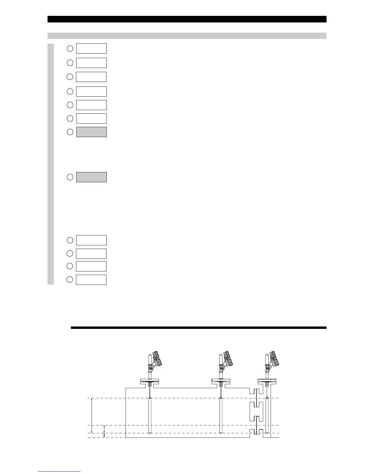
No offset
(Offset at 0 cm)
Positive offset
(Offset at 10 cm)
Negative offset
(Offset at -15 cm)
75 cm
100 %
0 %
15 cm
10 cm
20 mA = 75 cm
4 mA = 15 cm
20 mA = 85 cm
4 mA = 25 cm
20 mA = 60 cm
4 mA = 0 cm
OFFSET