16
For more details about the use of PACTware™ and FDT technology, refer to instruction manual 59-601
PACTware™ – Configuration and Troubleshooting
WHAT IS FDT, PACT
ware
™ AND DTM
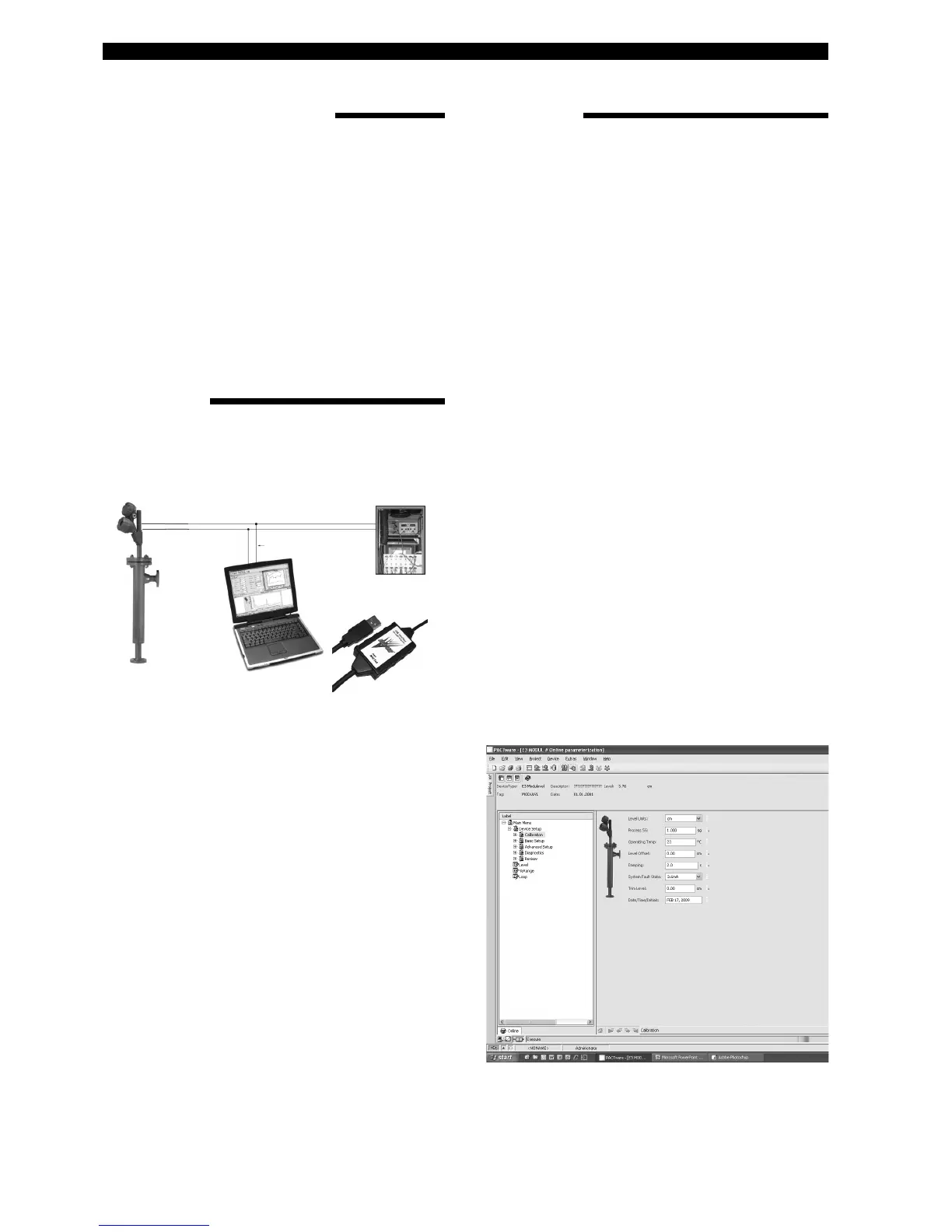
Power
HART connections
24 V DC
PC with
HART Serial
Interface
• FDT (Field Device Tool) is a new interface code that
describes the standardization between frame programs
(e.g., PACTware™) and DTMs (Device Type Manager).
• PACTware™ (Process Automation Configuration Tool)
is a frame program. It is a device-independent software
program that communicates with all approved DTMs.
• DTM (Device Type Manager) is a device-specific soft-
ware driver designed to operate within a FDT compatible
frame program such as PACTware™. It includes all spe-
cial information needed to communicate with a specific
device (e.g., Pulsar RX5). There are two basic categories
of DTM’s—Communication (HART, Fieldbus
®
, Profibus
®
,
etc.) and Field Device (e.g. Pulsar RX5 Radar transmit-
ter).
QUICK START
CONNECTIONS
1. Start a project
Open Pactware and add the Hart modem key and then
the Magnetrol instrument to your project.
Select: «Device» – «add device» – select device
(repeat for each device in your project)
Important: Make sure that the COM port settings for
y
our Hart modem key are correct;
2. Connect the devices
Select in the left window the Magnetrol instrument.
Select: «Device» – «connect» (both modem and
M
agnetrol instrument are getting connected)
3. Configure the instrument
Select: «Device» – «parameter» – «Online
parameterization»
O
pen «+ Main Menu» and select «+ Device set
up» – «Calibration»
Parameters can be changed in the window at right, via
the drop down boxes. ENTER confirms the change
online.
4. Manually calibrate the 4-20mA output
Select in «Calibration» - «Set point Calib» and
Select «Capture values».
A warning message appears to remove the loop from
DCS.
Set the 4mA (see MENU pages) «Capture 4mA»
Set the 20mA or 20 mA by % (see MENU pages)
«Capture 20mA», close the procedure by selecting
«End».
5. Diagnostics
E3 Modulevel offers the ability to monitor output and
LVDT position.
Select: «Device» – «parameter» – «Online
parameterization»
Open «+ Main Menu» and select «+ Device set
up» – «Diagnostics»
An overview is provided of all possible diagnostic val-
ues. A Print screen shot can, in case of field problems,
be sent for factory assistance. This screen also provides
a loop test function: 4mA, 20mA or any random mA test
value. Close the loop procedure by selecting «End».
The following diagram shows a typical hardware configura-
tion. Observe all safety codes when attaching to instrument
loops in hazardous areas or when measuring flammable
media. Computers are not intrinsically safe devices.
Magnetrol recom-
mends the VIATOR
®
USB HART
®
Interface
from MACTek
®
Corporation.