17
CONFIGURATION USING HART
®
I
MPORTANT: The digital HART
®
c
ommunication is superimposed on the
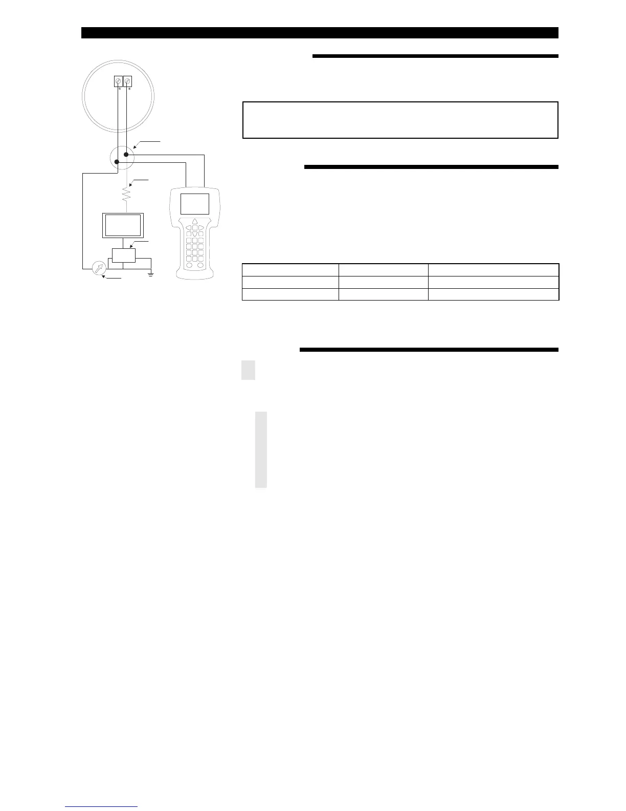
4-20 mA loop and requires a min. load resistance of 250 Ω and a max load
resistance of 450 Ω.
J
unction
C
ontrol
Room
Display
P
ower
Supply
C
urrent
Meter
R
L
>
250 Ω
CONNECTIONS
CHECK HART
®
Connection of your Hart communicator:
• at power terminals (+) and (-) in wiring compartment
• at first junction box between unit and control room.
Before starting the HART
®
configuration procedure – check if your HART
®
commu-
n
icator is equipped with the proper E3 Modulevel Device Descriptors (DD’s).
I/O start up the communicator
Select NO: go offline
Select 4: utility
Select 5: simulation
Check manufacturer: Magnetrol
HART MENU
I/O Start up the device
1 Enter Device Set Up «
DEVICE SET UP»
Press one of the following alphanumeric keys (if no key is sensed after 5 s, the
unit will automatically jump to RUN mode and alternatively show Level/% Output
and Loop signal
1 for entering Calibration «CALIBRATION» (see next page for additional infor-
mation)
2 for entering Basic Set Up «
BASIC SET UP» – general HART
3 for Advanced Set Up «
ADVANCED SET UP» (see next page for additional infor-
mation)
4 for entering Diagnostics «DIAGNOSTICS» (see next page for additional infor-
mation)
5 for entering Review «
REVIEW» to review all settings.
When the proper software version is not found, consult your local HART
®
Service
Center to load the correct E3 Modulevel DD’s.
HCF Release Date
HART Version Compatible with software
December 2007
Dev V1, DD V1 Version 1.0A through 1.0D
September 2011
Dev V2, DD V1 Version 1.1A and later