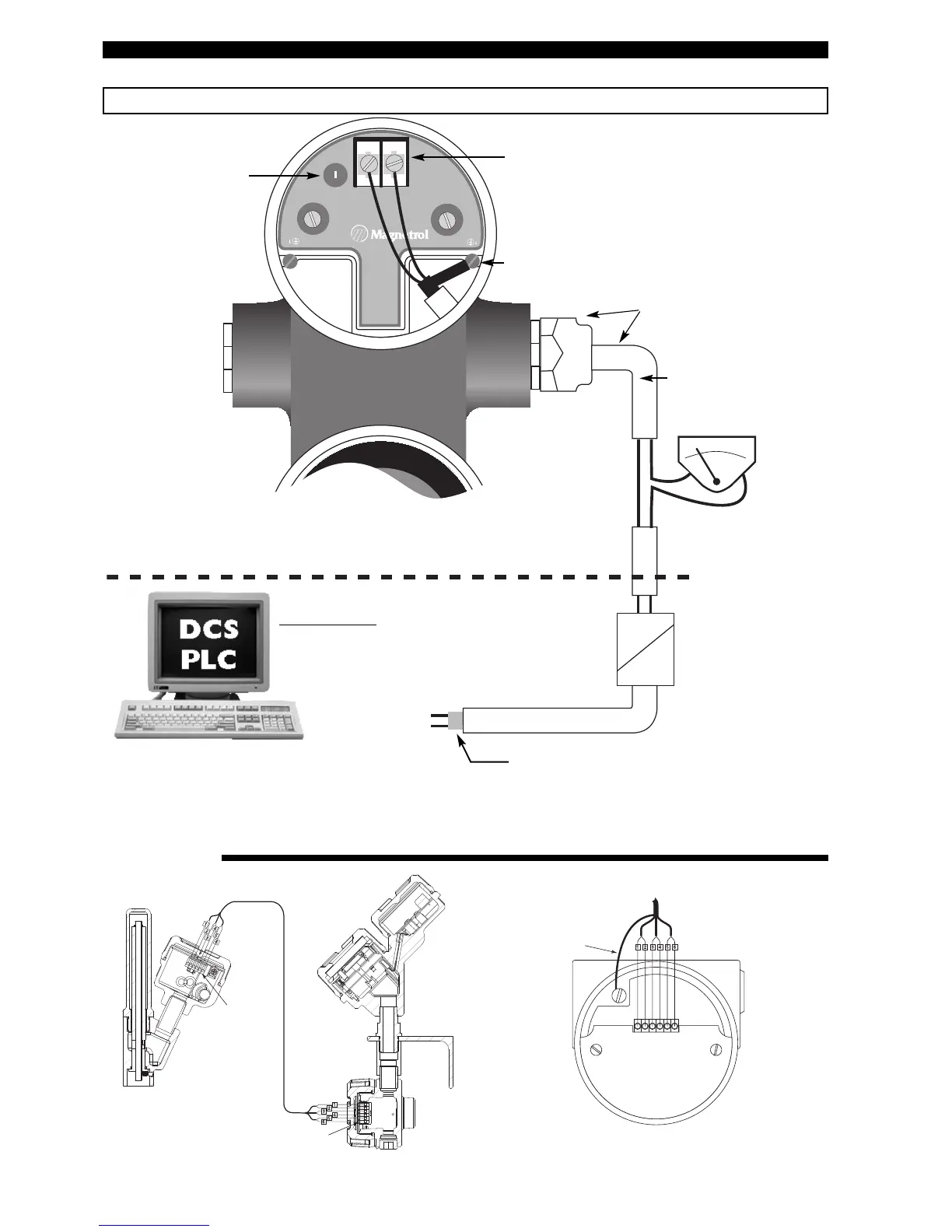
Positive supply to (+) terminal
Negative supply to (-) terminal
Shield wire to green grounding screw (resistance to
ground must be < 1 Ω).
Standard shielded twisted
pair cable recommended.
Use certified flameproof cable
gland(s) and cable for Explosion
proof area.
Galvanic Barrier:
(only needed for intrinsically safe units):
Hart
®
:
- ATEX/IEC: max 28,4 V DC @ 94 mA
- FM: max 28,6 V DC @ 140 mA
Foudation Fieldbus™: max 17,5 V DC @ 380 mA
ANALOG I/O
or
DIGITAL I/O
(only for units with HART)
Customer supplied
local current meter
Do not connect shield
Ex
Non Ex
Ex
Non Ex
Ex
Non Ex
IMPORTANT:
The shield wire should only be grounded at ONE side only. It is recommended to connect the shield to ground in the field (at
the transmitter side - as shown above) but connecting in the control room is also allowed.
REMOTE WIRING
Current loop test point
(Hart
®
only)
Integral
terminal board
Remote
terminal board
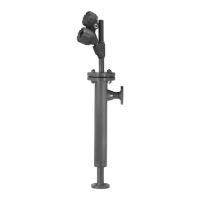
Integral wiring &
LVDT housings
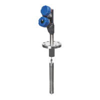
Remote wiring &
Transmitter housings
Shield wire to green grounding
screw at 1 side only
Match the numbered wires with the
numbers on each terminal block.