10
MENU: STEP BY STEP PROCEDURE – E3 Modulevel: Density control
= Wet calibration procedure
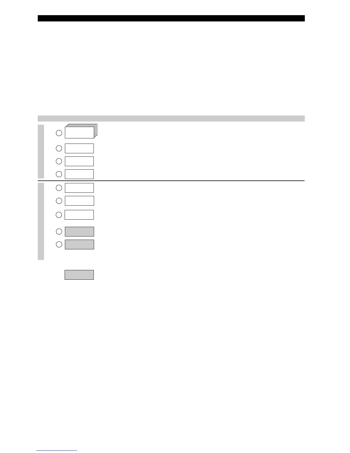
Screen Action Comment
Run mode
Configuration
1
2
3
4
8
9
*
Status*
*SG*
*%Output*
*
Loop*
SpecGrav
x.xx sg
%Output
xx.x%
Loop
xx.xx mA
5
OperTemp
xxx C
6
Set 4mA
xxx.x
Damping
xx sec
7
Set 20mA
xxx.x
Fault
(Select)
Transmitter Display
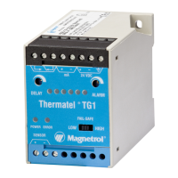
Transmitter default values cycle every 5 seconds. Status «Status»,
Density «SG», % Output «% Output», and Loop «Loop».
T
ransmitter Display
T
ransmitter displays Interface volume or interface level in selected
e
ngineering units (depending selection in Loop control «Loop Ctrl»
T
ransmitter Display
T
ransmitter displays % Output measurement derived from 20 mA
span.
Transmitter Display Transmitter displays Loop measurement (mA).
E
nter the process operating
temperature.
A
djusts factory calibration for actual temperature.
Enter the level value
for the 4 mA point.
Default value is “0”.
Enter the level value
for the 20 mA point.
Default value equals the displacer length.
Enter the damping factor. A Damping factor (1-45 seconds) may be added to smooth a noisy
display and/or output due to turbulence.
Enter the value for error.
Select «3.6 mA», «22 mA» or hold last value «HOLD». In case of
loop failure, error signal will follow the failing trend; meaning the unit
will show 3.6 mA when the reviewed loop current by the device is
found too low. The unit will show 22 mA in case the reviewed loop
current is found too high.
IMPORTANT:
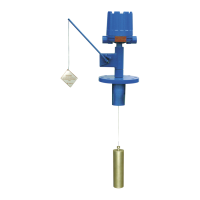
Units are pre-calibrated at the factory with 4mA at the bottom of the displacer (free hanging position) and 20mA at the top of
the displacer. If these settings match with the required settings, only enter operating temperature «OperTemp».
The displacer is specifically designed for the application and does not require any density setting.
Wet calibration is recommended in case the correct 4-20 mA levels can be simulated. In this case, do not use the screens
«set 4mA» and «Set 20mA» but proceed with the screens «Capture 4mA» and «Capture 20mA».
Correct output assumes no shift in level and the displacer at all times fully immerged in the liquid level (min. 50 mm (2")). See
page 12 for proper guidelines.
NOTE: For exchanging a new head or re-calibration of a unit with new spare parts, follow the User calibration proce-
dure (see page 15).