22
CAUTION: BENDING THE ENCLOSING TUBE
W
ILL PERMANENTLY DAMAGE THE UNIT.
MAINTENANCE
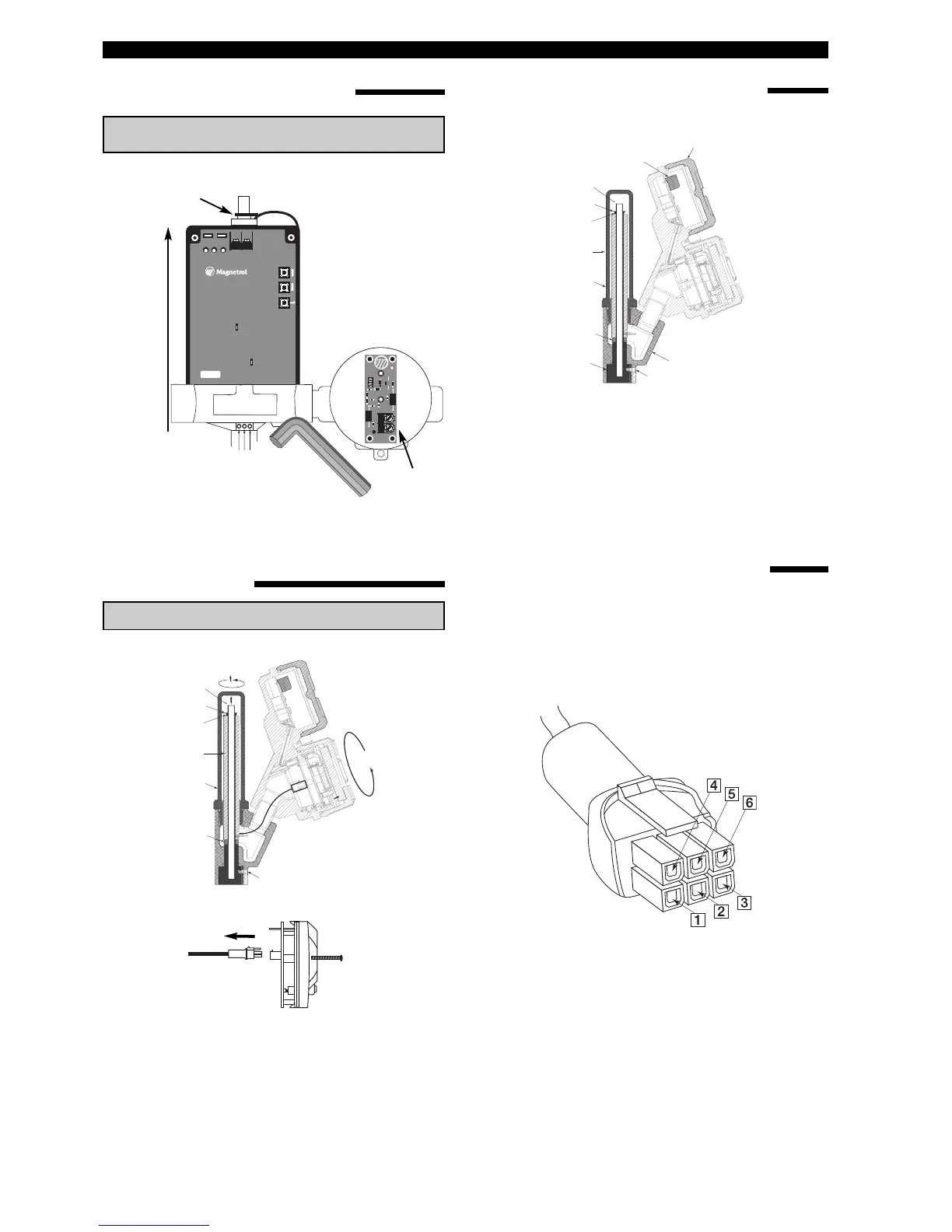
REMOVAL OF EZ TRANSMITTER HEAD
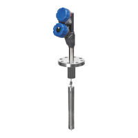
REPLACING WITH E3 TRANSMITTER HEAD
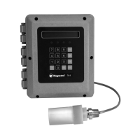
CHEKING THE LVDT WINDING RESISTANCE
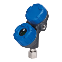
REPLACING LINEAR VARIABLE DIFFERENTIAL
TRANSFORMER (LVDT)
ENTER
UP
DOWN
ERROR
SPAN
ZERO
(–)
P2
(+)
P1
®
– TB1 +
E S MODULEVEL
®
5300 BELMONT ROAD,
DOWNERS GROVE, IL 60515,
USA.
HEIKENSSTRAAT 6,
B 9240 ZELE,
BELGIUM.
www.magnetrol.com
REFER TO MODULEVEL MANUAL,
BULLETIN 48-615, FOR
INSTALLATION AND OPERATION
INSTRUCTIONS.
TP1
TP2
J
1
05-9123-001
ASSEMBLY PART NO.
TB2
D1
P1
P2
C6 L5
C
5
C3
TB1
+
–
+
–
–
+
AW3175
L3
D2
JP1
L6
L4
L2
C1
C4
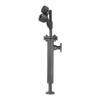
3 Unlock for repositioning or removal of
h
ead assembly and always relock,
after final positioning
4 Lift trans-
mitter head
o
ver
e
nclosing
tube
2 Remove grip ring
1 Remove cover
3 Remove LVDT
1 Disconnect
P
ower
S
ize 1/8"
1. Using a multimeter, check primary winding. Pins 1 and
4 should have approximately 75 to 105 Ω.
2. Secondary winding (pins 2 and 5 or 3 and 6) should
have approximately 70 to 100 Ω. If not in this range,
replace the LVDT.
2 Remove electronics
4 Remove LVDT cover
1
Remove the
LVDT housing
2 Remove C-ring,
use proper ring pliers
4 Loosen the set screws and remove the
dummy encolsing tube
6 Ensure that the flame path adaptor
is seated all the way down on the
E
-tube nut
7
Re-install LVDT top
spacer and C-ring
8
Rewire
the new head
Wiring compartment cover
5 Lower the new E3
h
ead on the LVDT
3 Remove LVDT top
s
pacer
7 Re-install in reverse way
5 Remove C-ring
6 Remove LVDT
LVDT top spacer
TFE
spacer
Set screws
Enclosing
tube
CAUTION: REMOVE POWER FIRST.
NOTE:
Remove transport enclosing tube before mounting
For calibration, use only the calibration procedure,
page 15.