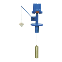
45-610 Displacer Type Liquid Level Switches and Proof-er
®
Switches
13
4.3 Specifications
Threaded Models ➃➄ 800 psig @ +100 °F (55 bar @ +38 °C)
250 psig @ +400 °F (17 bar @ +204 °C)
Flanged Models ➄ Limited to the pressure rating of the selected flange or displacer. Cast iron flanges are flat face type conforming to
ANSI dimensional specifications
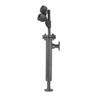
Low Pressure 25 psig @ +200 °F (1.7 bar @ +93 °C)
Proof-er Models
Medium Pressure 125 psig @ +300 °F (8.6 bar @ +149 °C)
Proof-er Models
➃ Models with stainless steel displacers are rated 720 psig @ +100 °F (50 bar @ +38 °C)
➄ Cryogenic construction available upon request. Consult factory with application details.
➀ With housing drain, CSA drops Group E and FM drops Group C.
➁ Models B10 and B15 with “HS” switches and all Model C10 and C15 are not ATEX approved.
➂ IEC Installation Instructions:
The cable entry and closing devices shall be Ex d certified suitable for the conditions of use
and correctly installed.
For ambient temperatures above +55 °C or for process temperatures above +150 °C, suitable
heat resistant cables shall be used.
Heat extensions (between process connection and housing) shall never be insulated.
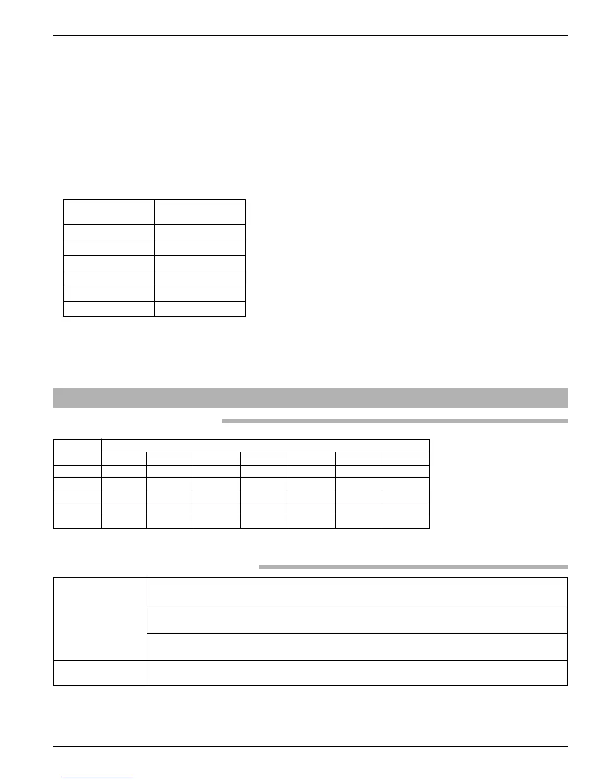
When the equipment is installed in process temperatures higher than +85 °C the temperature
classification must be reduced according to the following table as per IEC60079-0.
< 85 °C T6
< 100 °C T5
< 135 °C T4
< 200 °C T3
< 300 °C T2
< 450 °C T1
These units are in conformity with IECEx KEM 05.0020X
Classification Ex d IIC T6
T
ambient
-40° to +70 °C
120 VAC 15.00 15.00 10.00 2.50 5.00 15.00 15.00
240 VAC 15.00 15.00 — — 5.00 15.00 15.00
24 VDC 6.00 6.00 10.00 4.00 5.00 6.00 6.00
120 VDC 0.50 1.00 10.00 0.30 0.50 1.00 0.50
240 VDC 0.25 0.50 3.00 — 0.25 0.50 0.25