INSTRUCTION MANUAL AND PARTS LIST
DESCRIPTION
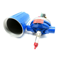
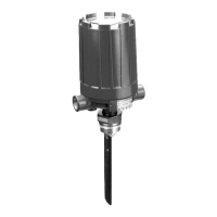
The F10 is a vane type flow switch designed to be installed
in 2" through 30" horizontal pipeline by means of a threaded
or flanged connection.
OPERATING PRINCIPLE
The actuating vane is magnetically linked to a pivoted
electric (or pneumatic) switch, which is isolated from the
process by a non-magnetic barrier tube. As the actuating
vane moves with an increase in flow, it drives a magnetic
sleeve ① into the field of a permanent magnet ② located
outside the barrier tube ③ which trips the switch. As flow
decreases, the actuating vane returns to a vertical position,
allowing the magnet and switch assembly to return to the
“No Flow” position.
Switch mechanism
Adjusting screw
M
agnetic sleeve
A
ctuating vane
M
agnet
NO FLOW
POSITION
POSITION WITH
ACTUATING FLOW PRESENT
AGENCY APPROVALS
Agency Approval
ATEX II 2G EEx d II C T6, explosion proof
II 1G EEx ia II C T6, intrinsically safe
CENELEC EEx d II C T6, explosion proof
CCE
➀
R1 (1) 136/MI/433, explosion proof
FM
Class I, Div. 1,Groups C & D
Class II, Div. 1,Groups E, F & G, Type NEMA 7/9
FM/CSA
➁
Non-Hazardous area
Explosion proof area –
Groups B, C, D, E, F & G Type NEMA 4X/7/9
SAA
➁
Explosion proof area
LRS Lloyds Register of Shipment (marine applications)
GOST/ Russian Authorisation Standards
GOSGORTECHNADZOR
➁
Other approvals are available, consult factory for more details
➀ For CCE approved units, use the ATEX explosion proof model
numbers.
➁ Consult factory for proper model numbers.