EasyManua.ls Logo

Magnetrol F10 User Manual

Magnetrol F10
28 pages
To Next Page IconTo Next Page
Page #1 background imageLoading...
Page #1 background image
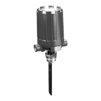
Model F10
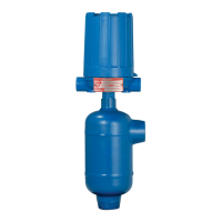
Model F50

Flow
Switches



Other manuals for Magnetrol F10

Questions and Answers:

Magnetrol F10 Specifications

General IconGeneral
CategorySwitch
TypeFloat
Material316 Stainless Steel
Connection Size1-1/2" NPT
Switch TypeSPDT

Summary

1.0 Introduction

1.0.1 Model F10

Introduces the F10 vane-actuated flow switches for various horizontal pipe applications.

1.0.2 Model F50

Describes F50 flow switches for sensing liquid flow in horizontal lines.

1.1 Principle of Operation

1.1.1 Model F10

Explains how flow pivots a vane, moving a sleeve to attract a magnet and actuate the switch.

1.1.2 Model F50

Details how flow moves a disc, raising a magnetic sleeve to actuate the switch.

1.2 Operating Cycle

1.2.1 Model F10

Describes how flow moves a vane, rotating a cam to lift an attraction sleeve and actuate the switch.

1.2.2 Model F50

Explains how increasing flow moves the attraction sleeve up, causing switch actuation.

2.0 Installation

2.1 Unpacking

Instructions for carefully unpacking and inspecting the instrument for damage or discrepancies.

2.2 Piping

2.2.1 Model F10

Guides on locating the F10 switch in a horizontal pipe with the arrow pointing in flow direction.

2.2.2 Model F50

Instructions for positioning the F50 switch in a horizontal pipe with the arrow in flow direction.

2.3 Mounting

2.3.1 Model F10 Mounting – Threaded Connection

Details threaded mounting for the F10, including pipe preparation and fitting.

2.3.1.1 Installation of F10 in Horizontal Line

Step-by-step guide for installing the F10 in a horizontal line using a threadolet fitting.

2.3.1.2 Positioning Vane Perpendicular to Flow

Instructions on positioning the F10's vane perpendicular to the flow for correct operation.

2.3.1.3 Trimming Vane to Fit Horizontal Line Size

Guidance on trimming the F10 vane to fit different horizontal line sizes (2-inch through 30-inch).

2.3.1.4 Final Mounting

Steps for final mounting of the F10, including sealing compound and connections.

2.3.2 Model F10 – Flanged Connection

Details flanged mounting for the F10, including alignment and housing position.

2.3.3 Model F50 Mounting

Instructions for mounting the F50 flow switch, ensuring vertical alignment.

2.3.3.1 Installation of Model F50

Specific steps for installing the F50, including alignment and avoiding stress on the housing.

2.4 Wiring

2.4.1 Model F10 Switch Actuation Adjustment

Explains how to adjust the F10 switch actuation flow rate using the adjusting screw.

3.0 Preventive Maintenance

3.1 Recommended Practice

Outlines the importance of periodic inspections for maintaining flow switch operability.

3.1.1 Keep Control Clean

Advises to keep the switch housing cover clean and in place for protection and safety.

3.1.2 Inspect Switch Mechanisms, Terminals, and Connections Monthly

Details monthly checks for switch mechanisms, terminals, and connections for wear and tightness.

3.1.3 Inspect Entire Unit Periodically

Recommends periodic inspection of the entire unit to check switch contact and reset functionality.

3.2 What To Avoid

4.0 Reference Information

4.1 Troubleshooting

Provides guidance on diagnosing and resolving common issues with the flow switches.

4.1.1 Check Switch Mechanism

Steps to check the switch mechanism for binding or misalignment issues.

4.1.2 Test Control's Performance

Describes how to test the control's performance after checking the switch mechanism.

4.2 Agency Approvals

4.3 Specific Gravity

4.3.1 Model F10 and F50 Specific Gravity Correction

Explains how to apply a specific gravity correction factor for liquids other than water.

4.4 Specifications

4.4.1 Model F10 Actuating Flow Rates

Provides actuating flow rates (GPM) for the Model F10 based on pipe line size.

4.4.2 Model F50 Actuating Flow Rates

Lists actuating flow rates (GPM) for the Model F50 by pipe size and flow rate designation.

4.4.3 Model F10 Dimensional Specifications

Presents dimensional data for the Model F10 with threaded and flanged connections.

4.4.4 Model F50 Dimensional Specifications

Provides dimensional specifications for the Model F50 with different pipe connections.

4.5 Replacement Parts

4.5.1 Model F10

Details replacement parts for the Model F10, including identification and reference.

4.5.1.1 Model F10 Parts Identification

Lists and identifies individual parts of the Model F10 flow switch with diagrams.

4.5.1.2 Model F10 Switch and Housing Reference

Provides a reference for different switch types and their corresponding bulletin numbers.

4.5.1.3 Model F10 Threaded Mounting

Lists replacement parts for Model F10 threaded mounting by material type and part number.

4.5.1.4 Model F10 Flanged Mounting

Lists replacement parts for Model F10 flanged mounting by material type and part number.

4.5.2 Model F50

Details replacement parts for the Model F50, including identification and reference.

4.5.2.1 Model F50 Parts Identification

Lists and identifies individual parts of the Model F50 flow switch with diagrams.

4.5.2.2 Model F50 Switch and Housing Reference

Provides a reference for different switch types and their corresponding bulletin numbers for F50.

4.5.2.3 Model F50 Bronze Body Replacement Parts

Lists replacement parts for F50 bronze body models by pipe size.

4.5.2.4 Model F50 Stainless Steel Body Replacement Parts

Lists replacement parts for F50 stainless steel body models by pipe size.

4.6 Model Numbers

4.6.1 Model F10

Explains the model number code for F10, including mounting, trim, magnetic sleeve, and pressure ratings.

4.6.2 Model F50

Details the model number code for F50, including body, trim, magnetic sleeve, and pressure ratings.

Service Policy

Return Material Procedure

Outlines the procedure for returning materials for service, including required information and cleaning.

Related product manuals