8
47-602 F10 and F50 Flow Switches
NOTE: For proper performance, a straight pipe run of 12 pipe diame-
ters up stream and 3 pipe diameters downstream of the switch
is recommended.
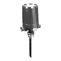
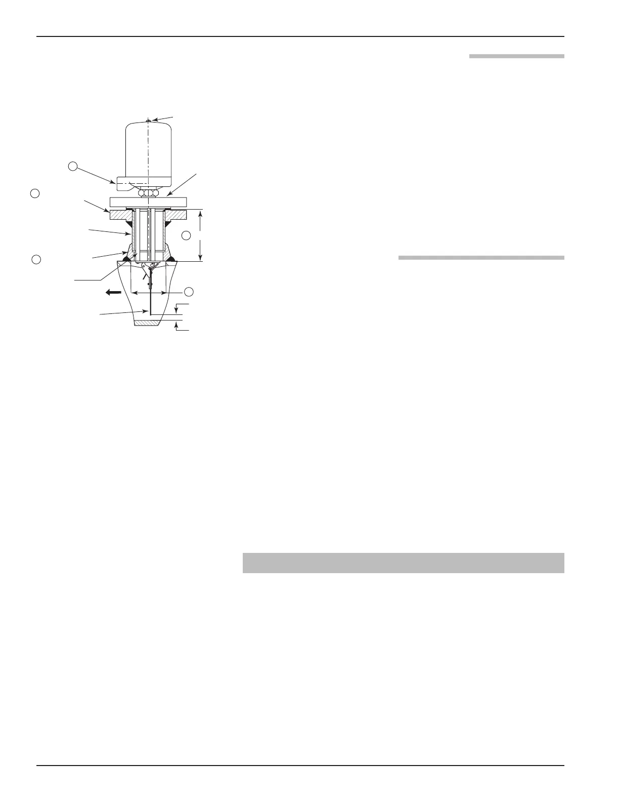
Figure 9 shows one method which may be used to mount
the F10 flow switch to 2
1
⁄2 to 30-inch run pipes. Before
final welding, alignment of mounting flange should be
checked to be certain it is plumb. Finished mounting must
allow control switch housing to be within three degrees of
vertical for proper operation. A three-degree slant is
noticeable by eye, but installation should be checked with
a spirit level.
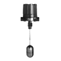
2.3.3.1 Installation of Model F50
1. When installing, use wrenches on valve body only. Do not
attempt to tighten or draw-up valve body on the pipe by
pulling or pushing on switch housing cover.
2. Adjust pipe alignment, as required, to bring switch hous-
ing to a vertical position above pipeline. F50 flow switches
must be mounted within three degrees of vertical. Three
degree slant is noticeable to the eye, but installation should
be check with a spirit level on the side of the enclosing
tube at two places, 90 degrees apart.
NOTE: On flow switches using pneumatic switch assemblies, con-
sult bulletin on mechanism furnished for air (or gas) piping
instructions.
NOTE: For proper performance, a straight pipe run (12 pipe diameters
upstream, and three pipe diameters downstream of the
switch), is recommended.
2.4 Wiring
Level controls are shipped from the factory with the
enclosing tube tightened and the middle set screw, on the
housing base, locked to the enclosing tube. Failure to
loosen the set screw prior to repositioning the conduit con-
nection may cause the enclosing tube to loosen, resulting
in the possible leakage of the process liquid or vapor.
NOTE: A switch or circuit breaker shall be installed in close proximity
to equipment and within easy reach of operator. It shall be
marked as the disconnecting device for the equipment.
Vertical centerline
must be plumb
2
1
/
2" ANSI
mounting
flange
2
1
/
2" P.S.
A
NSI flange
2
1
/
2" P.S.
p
ipe nipple
(sched. 80 max.
wall thickness)
2
1
/
2"- 3000 lb.
sockolet fitting
0
.19 minimum
3.00 dia. hole
in run pipe
Top of
run pipe
I
nside bottom
of run pipe
A
ctuating vane
F
LOW
1
2
3
5
4
5.25 (133)
Standoffs
(Qty. 3)
NOTES:
➀ Conduit outlet may be rotated 360° for wiring
convenience.
➁ Flange to match flange of F10 flow switch and
positioned with bolt holes straddling center
lines.
➂ For proper attachment procedure, refer to fitting
manufacturer’s recommendation.
➃ Dimension shown is for use with 0.06 inch
(2 mm) thick flange gasket. If thicker gasket is
used, reduce dimension amount equal to addi-
tional thickness.
➄ For run pipe sizes over 2.50 inch P.S. only. For
installation on 2.50 inch run pipes, disregard
3.00 inch dimension and use inside of adaptor
fitting as template.
≈ Follow appropriate sections under threaded
connection mounting to position the vane per-
pendicular to the flow and trim vane to size.