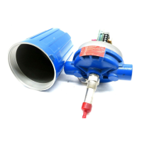
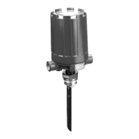
47-602 F10 and F50 Flow Switches
21
4.5 Replacement Parts
1
11
17
18
4
2
20
3
9
16
5
19
12
13
25
2
6
27
8
6
7
10
15
F
LO
1
11
17
18
4
2
20
14
23
24
22
21
3
9
16
5
19
12
13
25
26
27
8
6
7
10
15
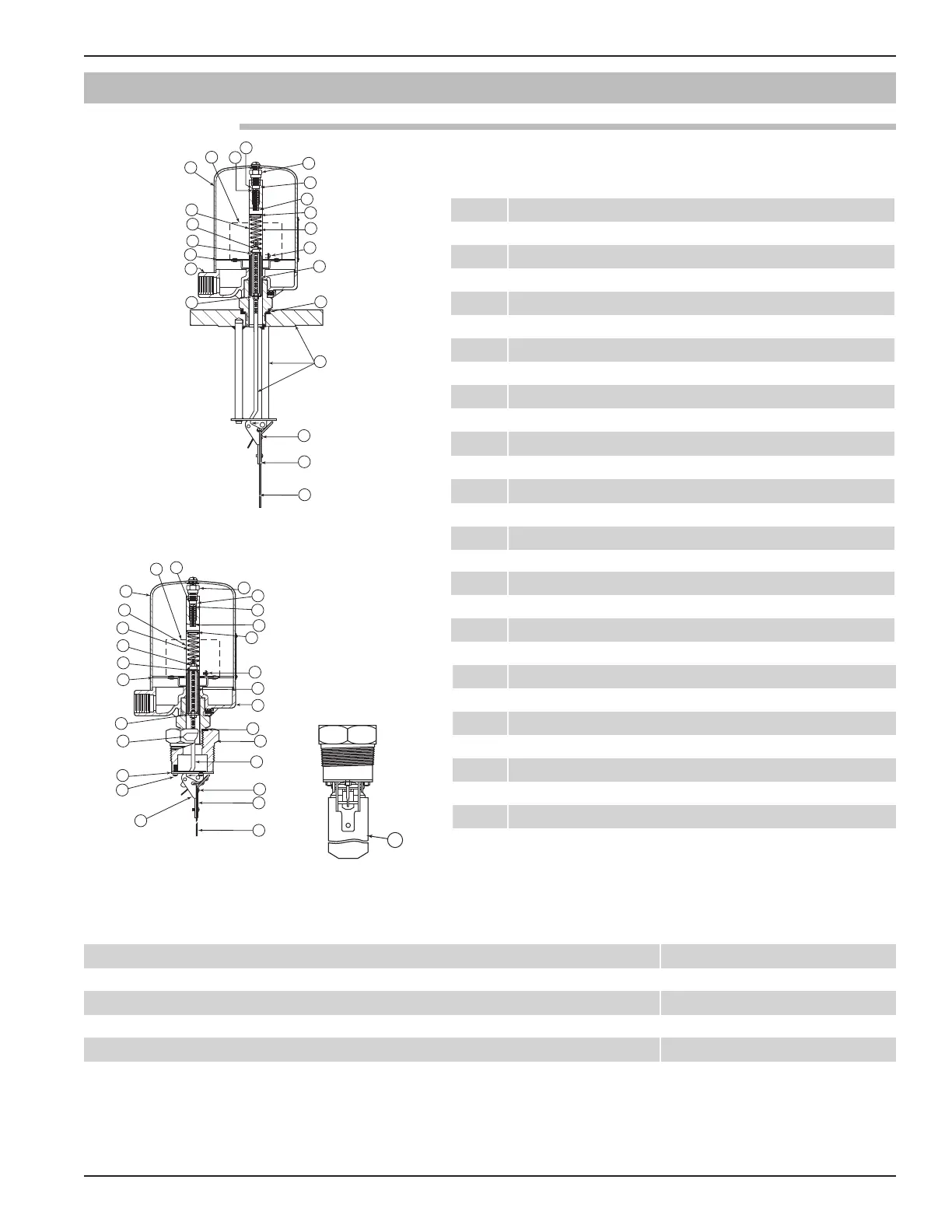
1 Housing cover
2 Housing base
3 Switch mechanisms
4 Baffle plate
5 6-32 round head screw
6 1/4-20 NPT plug
7 Safety retainer
8 Washer
9 O-ring
10 Adjustment screw
11 Enclosing tube
12 Enclosing tube gasket
13 Body bushing or stem, cam follower & flange assy.
14 Flow arrow
15 Upper spring guide
16 Range spring
17 10-32 hex nut
18 Lower spring guide
19 Attraction sleeve
20 Washer
21 Stem assembly
22 Cam assembly
23 No. 8 lock washer
24 8-32 fillister head screw
25 8-32 round head screw
26 Small vane
27 Large vane
4.5.1.1 Model F10 Parts Identification
Dry contact B, C, D 42-683
Hermetically sealed HS 42-694
Bleed type pneumatic J 42-685
Non-bleed type pneumatic K 42-686
4.5.1.2 Model F10 Switch and Housing Reference
When ordering replacement parts, please specify: A. Model and serial number of control.
B. Name and number of replacement part.
 Loading...