47-602 F10 and F50 Flow Switches
19
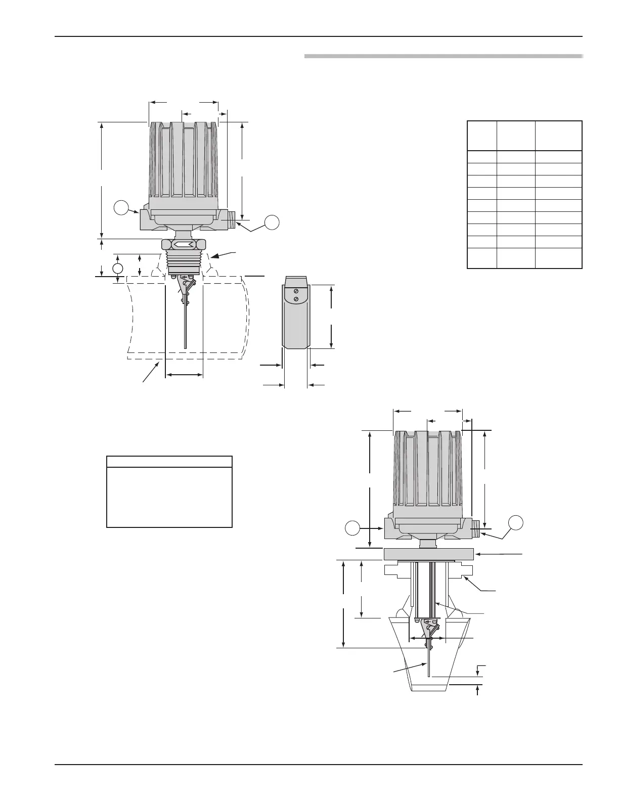
For proper performance, a straight pipe run of 12 pipe diameters upstream
and 3 pipe diameters downstream of the switch is recommended.
Ø 2.62 (67) ± .06 (2)
V
ane length dependent
upon line size
1.75
(44)
1.50
(38)
3" Pipe and Up
2" and 2 1/2" Pipe
2" NPT 3000# Bonney Threadolet
or Equal (Supplied by Customer)
Pipe Line Size
(Horizontal Lines Only)
Vane
Width
FLOW
A
5.93 (150)
3.87 (98)
8.46
(214)
A
plugged
B
1.56 (40)
2.50
(63)
10.12
(257)
Electrical Switches:
NEMA 4X/7/9: 1" NPT
Group B: 1" NPT
Pneumatic Switches:
NEMA 1:
1
/4" NPT
All housings rotatable 360°
2" 1.81 (46) 80
2
1
⁄2" 1.94 (49) 160
3" 1.88 (48) 80
3
1
⁄2" 1.88 (48) 80
4" 2.00 (51) 120
5" 2.06 (52) 120
6" 2.12 (54) 120
8" 2.19 (56) 100
Over
2.31 (59) —
8"
3.00 (76) Diameter
2 1/2" ANSI Flange
(to match F10)
2 1/2" ANSI
Mounting Flange
Flow Vane
0.19 (5) Minimum
5.93 (150)
3.87 (98)
8.46
(214)
10.12
(257)
plugged
5.25
(133)
Top of
pipe run
7.38
(187)
A
A
Standoffs (Qty. 3)
1. Allow the following for overhead
clearance for cover removal:
NEMA 1 — 8.00 (203)
NEMA 4X/7/9 — 10.00 (254)
Group B — 10.00 (254)