20
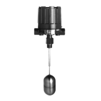
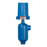
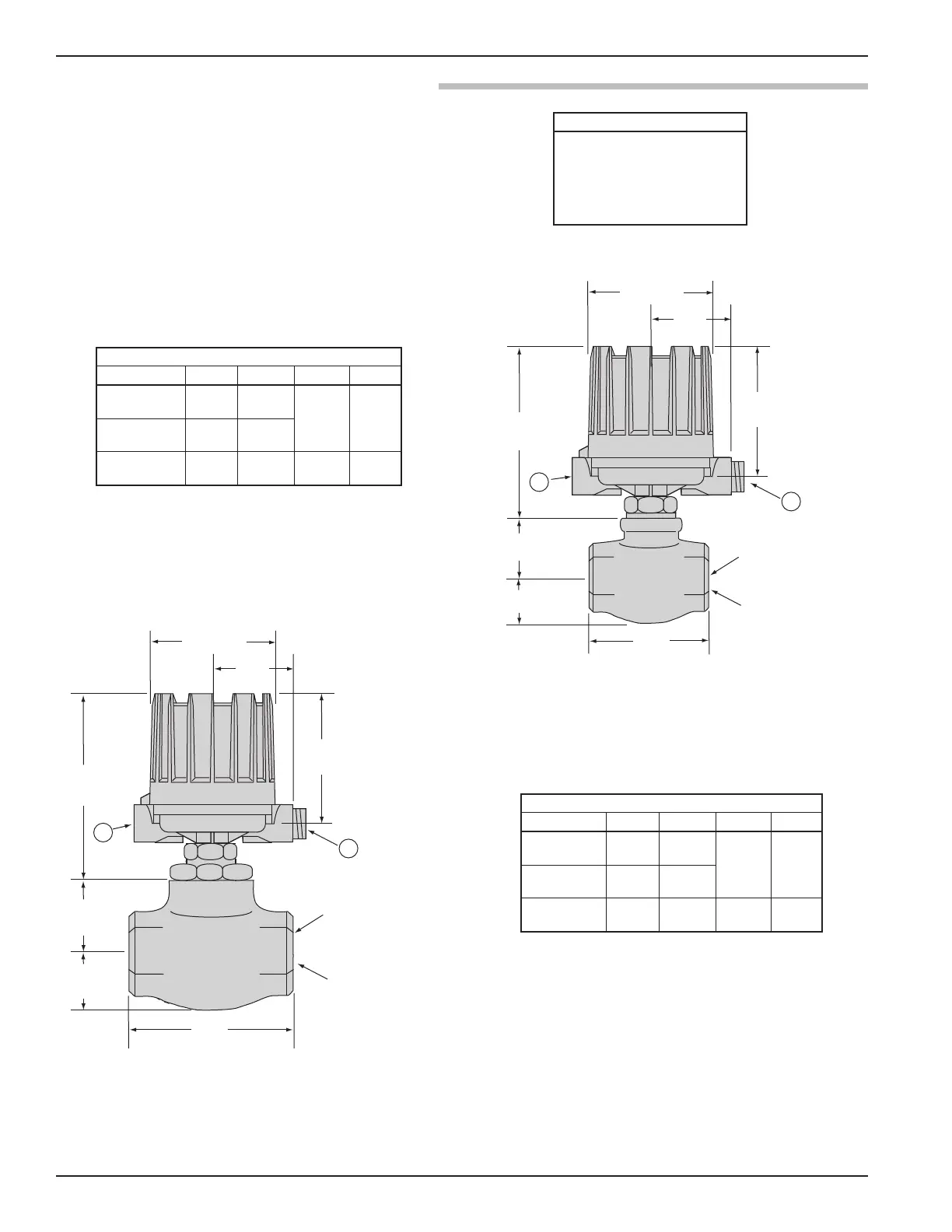
47-602 F10 and F50 Flow Switches
5.93 4.29
NEMA 4X/7/9
(151) (108)
NEMA 4X/7/9 5.93 4.29
9.75 3.60
Group B (151) (108)
(247) (91)
NEMA 1 4.70 5.00 8.44 3.44
Pneumatic (119) (127) (214) (87)
Electrical Switches
NEMA 4X/7/9: 1" NPT
Group B: 1" NPT
Pneumatic Switches
NEMA 1:
1
/4" NPT
*
5.93 4.29
NEMA 4X/7/9
(151) (108)
NEMA 4X/7/9 5.93 4.29
10.75 4.60
Group B (151) (108)
(273) (116)
NEMA 1 4.70 5.00 9.44 4.44
Pneumatic (119) (127) (240) (113)
1. For proper performance, a straight pipe run of 12 pipe
d
iameters upstream and 3 pipe diameters downstream of
the switch is recommended.
2. For NEMA 4X/7/9 allow 8.00 (203) overhead clearance for
cover removal.
6.25
(158)
*
3.87
(98)
5.93 (150)
7.94
(201)
*
3.00
(76)
2.00
(25)
5.75
(1.46)
Horizontal
lines only
Plugged
A
A
Connection size NPT
(both ends)
6.25
(158)
*
3.87
(98)
5.93 (150)
7.94
(201)
*
3.18
(80)
1.19 (30)
3.81
(97)
Horizontal
lines only
Plugged
A
A
Connection size NPT
(both ends)
* This dimension increases by 2.19" (55) when the
unit is supplied with an HS hermetically sealed
switch with terminal block
* This dimension increases by 2.19" (55) when the
unit is supplied with an HS hermetically sealed
switch with terminal block