EasyManua.ls Logo

Magnetrol 75 Series User Manual

Magnetrol 75 Series
14 pages
To Next Page IconTo Next Page
Page #1 background imageLoading...
Page #1 background image
SERIES 75
Liquid Level Switches
®
INSTRUCTION MANUAL AND REPLACEMENT PARTS
DESCRIPTION
Magnetrol’s Series 75 level switches are float operated
units suitable for use on clean liquid applications for level
alarm, pump control and safety shutdown functions.
OPERATING PRINCIPLE
A permanent magnet is attached to a pivoted switch
actuator
. As the float/ displacer rises following the liq-
uid level, it raises the attraction sleeve
into the field of the
magnet, which then snaps against the non-magnetic
enclosing tube
, actuating the switch. The enclosing tube
provides a static pressure boundary between the switch
mechanism and the process. On a falling level, an inconel
spring retracts the magnet, deactivating the switch.
Rising level Falling level
pivot
return spring
UNPACKING
Unpack the instrument carefully. Inspect all units for dam-
age. Report any concealed damage to carrier within 24
hours. Check the contents of the packing slip and purchase
order. Check and record the serial number for future refer-
ence when ordering parts.
AGENCY APPROVALS
Agency Approval
CENELEC EEx d IIC T6, explosion proof
EEx ia IIC T6, intrinsically safe
BASEEFA Ex d IIC T6
CSA Non-Hazardous CSA Type 4X
Class I, Div. 2, Groups B, C & D
Class I, Div. 1, Groups C & D
Class II, Div. 1, Groups E, F & G
Class I, Div. 1, Groups B, C & D
Class II, Div. 1, Groups E, F & G
FM Non-Hazardous NEMA 4X
Class I, Div. 1, Groups C & D
Class II, Div. 1, Groups E, F & G
Class I, Div. 1, Groups B, C & D,
Class II, Div. 1, Groups E, F & G
SAA Ex d IIC T6 (IP65)
Not available with all switches; Consult factory for proper
model numbers.
Consult factory for proper model numbers.
Question and Answer IconNeed help?

Do you have a question about the Magnetrol 75 Series and is the answer not in the manual?

Magnetrol 75 Series Specifications

General IconGeneral
BrandMagnetrol
Model75 Series
CategorySwitch
LanguageEnglish

Summary

DESCRIPTION

OPERATING PRINCIPLE

Explains the magnetic attraction mechanism for actuating the switch based on liquid level changes.

AGENCY APPROVALS

Lists various agency approvals including CENELEC, BASEEFA, CSA, and FM for hazardous and non-hazardous locations.

UNPACKING

Instructions for carefully unpacking the instrument, inspecting for damage, and recording the serial number.

MODEL IDENTIFICATION

MATERIALS OF CONSTRUCTION

Details the available materials for chambers, floats, and sleeves used in the models.

SIZE AND TYPE OF TANK CONNECTIONS

Specifies connection types (Threaded, Socket weld, Flange) and sizes for tank mounting.

SWITCH MECHANISM AND ENCLOSURE

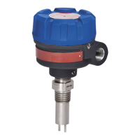
Refers to other pages for pneumatic and electric switch mechanisms and enclosures.

SELECT SWITCH MECHANISM & ENCLOSURE

Series A - Mercury switch (250°F)

Details for Series A mercury switch with a maximum temperature rating of 250°F.

Series B - Mercury switch (150°F)

Details for Series B mercury switch with a maximum temperature rating of 150°F.

Series C - Snap switch (120°F)

Details for Series C snap switch with a maximum temperature rating of 120°F.

Series D - Snap switch (230°F)

Details for Series D snap switch with a maximum temperature rating of 230°F.

Series E - Vibration switch (250°F)

Details for Series E vibration switch with a maximum temperature rating of 250°F.

Series F - Mercury switch (150°F)

Details for Series F mercury switch with a maximum temperature rating of 150°F.

Series G - Snap switch (75°F)

Details for Series G snap switch with a maximum temperature rating of 75°F.

Series H - Mercury switch (150°F)

Details for Series H mercury switch with a maximum temperature rating of 150°F.

Series S - Snap switch (75°F)

Details for Series S snap switch with a maximum temperature rating of 75°F.

Series W - Mercury switch (150°F)

Details for Series W mercury switch with a maximum temperature rating of 150°F.

Series X - Mercury switch (230°F)

Details for Series X mercury switch with a maximum temperature rating of 230°F.

Series Y - Mercury switch (230°F)

Details for Series Y mercury switch with a maximum temperature rating of 230°F.

Series Z - Mercury switch (230°F)

Details for Series Z mercury switch with a maximum temperature rating of 230°F.

Series H - Hemetically sealed (150°F)

Details for Series H hermetically sealed switch with a maximum temperature rating of 150°F.

Series W - Hemetically sealed (150°F)

Details for Series W hermetically sealed switch with a maximum temperature rating of 150°F.

Series X - Hemetically sealed (230°F)

Details for Series X hermetically sealed switch with a maximum temperature rating of 230°F.

Series Y - Hemetically sealed (230°F)

Details for Series Y hermetically sealed switch with a maximum temperature rating of 230°F.

Series Z - Hemetically sealed (230°F)

Details for Series Z hermetically sealed switch with a maximum temperature rating of 230°F.

Series S - Hemetically sealed (75°F)

Details for Series S hermetically sealed switch with a maximum temperature rating of 75°F.

INSTALLATION

PIPING

Guidance on piping installation for the control, emphasizing support and avoiding low spots.

MOUNTING

Instructions for mounting the control, requiring a vertical position within three degrees of vertical.

WIRING

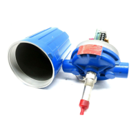
Procedures for wiring the control, including access to switch mechanisms and terminal connections.

SWITCH DIFFERENTIAL ADJUSTMENT

PREVENTIVE MAINTENANCE

TROUBLESHOOTING

CHECK SWITCH MECHANISM

Steps to diagnose issues with the switch mechanism, including checking for binding or damage.

CHECK SENSING UNIT

Procedure for checking the sensing unit for liquid flow, corrosion, or float issues.

CHECK COMPLETE UNIT

Final checks on the entire control unit after reassembly to ensure proper operation.

ACTUATING LEVELS

SEALED CAGE MODEL DIMENSIONAL SPECIFICATIONS

REPLACEMENT PARTS

SERIES 75 TANDEM FLOAT UNITS DESCRIPTION

INSTALLATION, PREVENTATIVE MAINTENANCE AND TROUBLE SHOOTING

Covers installation, maintenance, and troubleshooting for tandem float models.

DIFFERENTIAL ADJUSTMENT

Notes that differential adjustment is factory set for tandem models and should not be altered in the field.

REPLACEMENT OF FLOAT AND STEM ASSEMBLIES

Guidance on replacing float and stem assemblies, recommending replacement of the entire sensing unit.

REPLACEMENT PARTS

Lists standard replacement assembly kits for tandem float units.

SERVICE POLICY

RETURNED MATERIAL PROCEDURE

Details the procedure for returning materials for repair or replacement, including RMA requirements.

Related product manuals