EasyManua.ls Logo

Magnetrol F50 - User Manual

Magnetrol F50
8 pages
Print Icon
To Next Page IconTo Next Page
Loading...
Description
F50 Flow Switches are utilized, in horizontal lines, to sense
the start or stop of liquid flow in oil, chemical, gas, and
water lines.
Principle of operation
The rate of flow through the valve body raises or lowers the
disc. This in turn raises or lowers the magnetic sleeve, with-
in its sealed non-magnetic enclosing tube. On an increasing
flow rate, the magnetic sleeve rises into the field of the per-
manent magnet, located outside the enclosing tube, actuat-
ing the attached switch mechanism. When the flow rate
drops, below the rate for which the flow disc is calibrated, a
reversal of this action occurs.
Operating cycle
On an increasing flow rate, the flow disc moves the attrac-
tion sleeve up within the field of a switch magnet, drawing it
in tightly to the enclosing tube. This causes the switch to
make or break an electrical circuit. When the flow rate
drops, below the rate for which the flow disc is calibrated,
the attraction sleeve is pulled downward until, at a predeter-
mined low flow rate, the switch magnet releases and swings
outward, away from the enclosing tube, causing a reversal
of the switching action.
Figure 1 Figure 2
5
6
4
Mercury switch
Swing out
position
Tension
spring
Pivot
No flow
position
5
6
4
Enclosing tube
(Non-magnetic)
Swing in
position
Sleeve
(magnetic)
Magnet
Flow disc
Position with
actuating flow
present
F50 Flow Switch
Instruction Manual and Parts List
Question and Answer IconNeed help?

Do you have a question about the Magnetrol F50 and is the answer not in the manual?

Overview

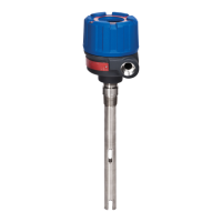
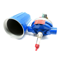
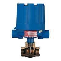
The F50 Flow Switch is a device designed to sense the start or stop of liquid flow in horizontal oil, chemical, gas, and water lines. It operates on a principle where the flow rate through the valve body raises or lowers a disc, which in turn raises or lowers a magnetic sleeve within a sealed non-magnetic enclosing tube. On increasing flow, the magnetic sleeve rises into the field of a permanent magnet, actuating an attached switch mechanism. When flow drops below the calibrated rate, the action reverses.

Operating Cycle:

During increasing flow, the flow disc moves an attraction sleeve up into the field of a switch magnet, drawing it tightly to the enclosing tube. This action makes or breaks an electrical circuit. When the flow rate decreases below the calibrated rate, the attraction sleeve is pulled downward until the switch magnet releases and swings outward from the enclosing tube, reversing the switching action.

Technical Specifications:

Materials of Construction:

  • Bronze Body: Type 300 series stainless steel trim; 400 series stainless steel magnetic sleeve.
  • Stainless Steel Body: Type 316 stainless steel body and all internal trim.

Pipe Sizes (NPT):

  • 3/4", 1", 1 1/2", 2"

Actuating Flow Rates (GPM Water Flow):

Flow rates vary by pipe size and flow disc calibration (A to F).

  • 3/4" NPT:
    • Increasing: 1.1 - 4.9 GPM
    • Decreasing: 0.8 - 3.7 GPM
  • 1" NPT:
    • Increasing: 1.0 - 7.1 GPM
    • Decreasing: 0.8 - 5.8 GPM
  • 1 1/2" NPT:
    • Increasing: 1.3 - 21.1 GPM
    • Decreasing: 1.1 - 17.9 GPM
  • 2" NPT:
    • Increasing: 1.9 - 24.8 GPM
    • Decreasing: 1.6 - 21.0 GPM

Specific Gravity Correction:

For liquids other than water (viscosity ≤ 20 centistokes), a specific gravity correction factor must be applied to the water flow rates. For example, a liquid with 0.60 specific gravity has a multiplication factor of 1.33.

Electronic Switch Mechanism & Enclosure:

  • Max Process Temperature:
    • Mercury Switches (Series A, E): 550°F (288°C)
    • Snap Switches (Series B, D): 250°F (121°C)
    • Snap Switches (Series C): 450°F (232°C)
    • HS Hermetically Sealed Switches: 550°F (288°C)
    • Bronze models are rated up to 500°F (260°C). Stainless steel models are limited by the switch mechanism's max temperature.
    • On condensing applications, temperature is down-rated to 400°F (204°C) process at 100°F (38°C) ambient.
  • Switch Types: SPDT, DPDT (Mercury, Snap, Vibration Resistant Mercury, Hermetically Sealed Snap).
  • Enclosures: NEMA 4X, NEMA 4X/7/9, Class I Div. 1 Group B.
  • Conduit Connections: 1" NPT for electrical switches (NEMA 4X, NEMA 4X/7/9, Group B); 1/4" NPT for pneumatic switches (NEMA 1).

Pneumatic Switch Mechanism & Enclosure:

  • Max Process Temperature: 400°F (204°C)
  • Max Supply Pressure:
    • Bleed Type (Series J): 100 PSIG (7 Bar) or 60 PSIG (4 Bar)
    • Non-Bleed Type (Series K): 100 PSIG (7 Bar) or 40 PSIG (3 Bar)
  • Bleed Orifice Diameter: 0.63" (1.6 mm) or 0.94" (2.4 mm)
  • Enclosure: NEMA 1

Usage Features:

Installation:

  • Location: Horizontal pipe run, with the arrow on the valve body pointing in the direction of flow. The switch housing must always be above the valve body.
  • Alignment: Must be mounted within three degrees (3°) of vertical. Check with a spirit level on the side of the switch housing cover at two places, 90° apart.
  • Wrench Use: Use wrenches on the valve body only. Do not attempt to tighten or draw-up the valve body by pulling or pushing on the switch housing cover.
  • Pipe Alignment: Adjust pipe alignment to bring the switch housing to a vertical position.
  • Straight Pipe Run: A straight pipe run (12 pipe diameters upstream and three pipe diameters downstream of the switch) is recommended for proper performance.
  • Conduit Connection: Loosen the middle set screw on the housing base, locked to the enclosing tube, before repositioning the conduit connection to prevent leakage of process liquid or vapor.
  • Wiring:
    • For high-temperature applications (above 250°F [121°C]), use high-temperature insulated wire between the F50 and the first junction box in a cooler area.
    • Remove the switch housing cover to access the mechanism.
    • Pull in supply wires, wrap them around the enclosing tube underneath the baffle plate, and connect to terminals. Ensure adequate clearance for switch tilt and cover replacement.
    • Connect power supply and test switch actuation by varying flow rate.
    • If the switch mechanism fails to function, check vertical alignment and refer to the installation bulletin.
    • Replace the switch housing cover and place the flow switch into service.

Maintenance Features:

Troubleshooting:

  • External Causes: Check for blown fuses, reset buttons needing resetting, open power switch, or faulty controlled equipment.
  • Switch Mechanism Check:
    • Deactivate electrical circuits.
    • Remove the switch housing cover.
    • Swing the magnet assembly by hand, checking for binding. It should move through its full swing with minimal force.
    • If binding exists, the magnet may be rubbing the enclosing tube, or pivot sockets may be overly tight. Readjust pivot sockets for slight side play. If the magnet is rubbing, loosen the magnet clamp screw and shift the magnet position.
    • If the mechanism still fails to actuate, check the control's vertical installation (within 3°).
    • If equipped with a mercury switch, examine the glass tube for damage and replace it immediately if necessary. Spare switches should be kept on hand.
  • Control Performance Check:
    • Reconnect power supply and manually actuate the switch mechanism with a non-conductive tool to check if controlled equipment operates.
    • If controlled equipment responds, trouble may be in the flow sensing portion. Check if liquid is flowing through the pipeline (valve closed or pipeline plugged).
  • Magnet Failure:
    • If the magnet fails to pull in on increasing flow: check for too small a disk diameter, hang-up or deposits in the disk seat, or malfunctioning by manually moving the magnet carriage.
    • If the magnet fails to pull out on decreasing flow: check for too large a disk diameter, hang-up or deposits in the disk seat, or malfunctioning by manually moving the magnet carriage.

Preventive Maintenance:

  • Keep Control Clean: Ensure the switch housing cover is always in place to protect against dust, dirt, moisture, and to act as a safety feature. Replace damaged covers or seals immediately.
  • Inspect Switch Mechanisms, Terminals, and Connections (Monthly):
    • Mercury Switches: Visually inspect for short circuit damage or small cracks in the glass tube. Oxidized mercury (dirty or dull, not forming clean, round pools) indicates damage; replace immediately.
    • Dry Contact Switches: Inspect for excessive wear on the actuating lever or misalignment of the adjustment screw. Adjust or replace the switch if necessary.
    • Wiring: Check for brittle insulation, especially in high heat or moisture conditions, and replace at the first sign of damage.
    • Terminal Screws: Check for loose terminal screws due to vibration and tighten as needed.
    • Pneumatic Switches: Inspect air/gas operating lines for cracks or loose connections due to vibration; repair or replace as needed.
  • Inspect Entire Unit Periodically: Isolate the control from the vessel and raise/lower the liquid level to check for switch contact and reset.
  • What to Avoid:
    • Never leave the switch housing cover off longer than necessary.
    • Never place a jumper wire across terminals to cut out the control.
    • Never attempt adjustments or switch replacements without reading instructions. Consult the factory or representative if in doubt.
    • Never use lubricants on switch mechanism pivots. Sufficient lubricant is applied at the factory for lifetime service; further lubrication attracts dust and dirt.

Magnetrol F50 Specifications

General IconGeneral
BrandMagnetrol
ModelF50
CategorySwitch
LanguageEnglish

Related product manuals