Wiring
1. On high temperature applications (above 250°F [121°C]
in pipeline), high temperature insulated wire should be
used between the F50 and the first junction box, located
in a cooler area.
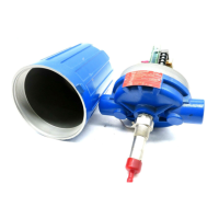
2. To gain access to the switch mechanism, remove switch
housing cover.
3. Pull in supply wires (conductors), wrap around enclosing
tube underneath the baffle plate, and connect to proper
terminals. Be certain that excess wire does not interfere
with tilt of switch, and that adequate clearance exists for
replacement of switch housing cover.
NOTE: See switch mechanism bulletin, which is furnished
with your control, for proper connections. Refer to the chart
on page 7 for the proper bulletin number.
4. Connect power supply to the F50, and test switch actua-
tion by varying flow rate within pipeline.
NOTE: If the switch mechanism fails to function properly,
check vertical alignment of control housing, and refer to
installation bulletin on mechanism furnished, as listed on
page 7.
5. Replace switch housing cover, and place flow switch into
service.
INSTALLATION
TROUBLESHOOTING
4
Piping
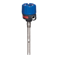
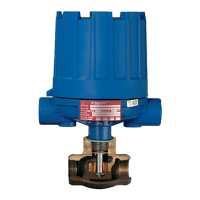
The Model F50 flow switch should be located in a horizon-
tal pipe run, with the arrow on the valve body pointing in the
direction of flow. The switch housing must always be above
the valve body.
1. When installing, use wrenches on valve body only. Do
not attempt to tighten or draw-up valve body on the pipe
by pulling or pushing on switch housing cover.
2
. Adjust pipe alignment, as required, to bring switch hous-
ing to a vertical position above pipeline. F50 flow switches
must be mounted within three degrees (3°) of vertical.
Three degree slant is noticeable to the eye, but installation
should be check with a spirit level on the side of the
switch housing cover at two places, 90° apart.
NOTE: On flow switches using pneumatic switch assem-
blies, consult bulletin on mechanism furnished for air
(or gas) piping instructions.
NOTE: For proper performance, a straight pipe run (12 pipe
diameters upstream, and three pipe diameters downstream
of the switch), is recommended.
Usually the first indication of improper operation is failure of
the controlled equipment to function, i.e., pump will not
start (or stop), signal lights fail to light, etc. When these
symptoms occur, whether at time of installation or during
routine service thereafter, check the following potential
external causes first.
– Fuses may be blown.
– Reset button(s) may need resetting.
– Power switch may be open.
– Controlled equipment may be faulty.
If a thorough inspection of these possible conditions fails to
locate the trouble, proceed to a check of the control's
switch mechanism.
1. Pull disconnect switch, or otherwise assure that electri-
cal circuit(s) of control are deactivated.
2. Remove switch housing cover.
3. Swing magnet assembly in and out by hand, checking
carefully for any sign of binding. Assembly should require
minimal force to move it through its full swing.
4. If binding exists, magnet may be rubbing enclosing tube,
or pivot sockets may be overly tight. Readjust pivot
sockets as required, until a slight amount of side play is
evident. If magnet is rubbing, loosen magnet clamp
screw, and shift magnet position.
5. If switch magnet assembly swings freely, and mecha-
nism still fails to actuate, check installation of control to
be certain it is within the specified three degrees (3°) of
vertical. Use a spirit level on side of enclosing tube in
two places, 90° apart.
6. If mechanism is equipped with a mercury switch, exam-
ine glass mercury tube closely. If switch is damaged,
replace it immediately.
NOTE: As a matter of good practice, spare switches should
be kept on hand at all times.
CAUTION: Model F50 flow controls are shipped from the
factory with the enclosing tube tightened and the middle
set screw, on the housing base, locked to the enclosing
t
ube. Failure to loosen the set screw prior to reposition-
ing the conduit connection may ca use the enclosing
tube to loosen, resultin g in the possible leakage of the
process liquid or vapor.
 Loading...