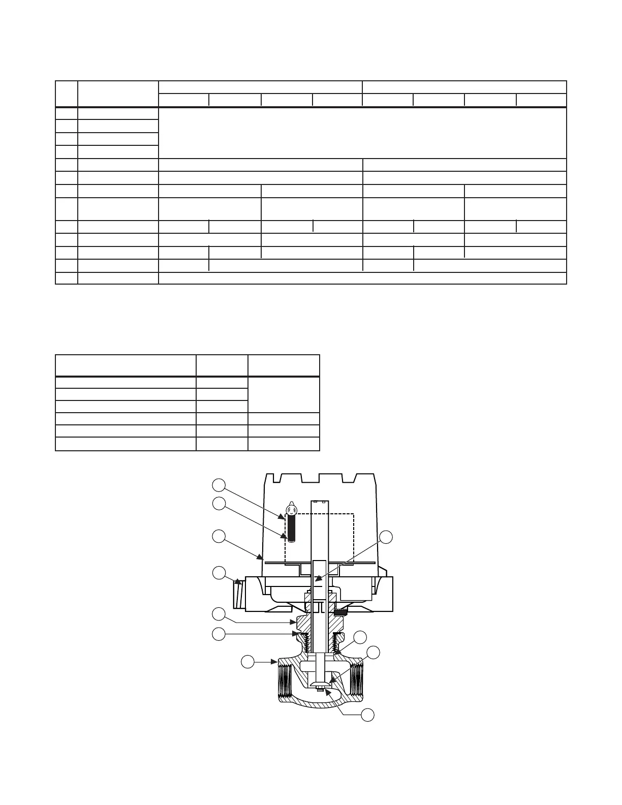
REPLACEMENT PARTS
Item
Description
Bronze Body Stainless Steel Body
No.
3
/4" 1" 1
1
/2" 2"
3
/4" 1" 1
1
/2" 2"
1 Housing Cover
2 Housing Base
Refer to chart below for appropriate bulletin number on
3 Switch Mechanism
switch mechanism and housing replacement assemblies.
4 Switch
5 Enclosing Tube 32-6325-002 32-6325-002
6 E-Tube Gasket 12-1204-001 12-1204-001
7 O Ring (not shown) Not required 12-1204-036 Not Required 12-1204-036
8
Body Adaptor
Not Required 04-0481-001 Not Required 04-0481-001
(not shown)
9 Threaded Body 02-5703-003 02-5703-004 02-5705-003 02-5705-004 02-5703-001 02-5703-002 02-5705-001 02-5705-002
10 Flow Piston Stop 05-5420-121 Not Required 05-5420-121 Not Required
11 Flow Piston Assy. 32-7127-001 32-7127-003 32-7127-002 32-7108-001 32-7109-001 32-7109-002
12 Lock Nut 10-2107-002 10-2107-003 10-2107-002 10-2107-003
13 Flow Disc Specify complete model number.
Switch Mechanism
Series
Reference
Bulletin
Mercury Switch A, 3
Dry Contact Switches B, C, D 42-683
Vibration Resistant Mercury Switch E, 2
Hermetically Sealed Snap Switch HS 42-694
Bleed Type Pneumatic Valve J 42-685
Non-Bleed Type Pneumatic Valve K 42-686
Highly corrosive applications use piston assembly with sheathed attraction sleeve. Consult local representative for ordering assistance.
Use insoluble adhesive on nut when attaching new flow disc.
When actuated flow rate is critical, the entire control must be returned to the factory for replacement and recalibration of flow disc.
IMPORTANT:
When ordering, please specify:
A. Model and serial number of control.
B. Name and number of replacement part.
7