Installation
D1 0223TH1-GB01 5
This Technical Handbook is to be used exclusively by trained service personnel.
Regulations and guidelines in the Operating Manual listed under section "Safety" apply
in all cases!
1 Installation
Installation errors may show up months after actual installation. Warranty does not
cover installation errors.
Incorrect wiring and screening can result in data loss due to reflections.
Adhere to the following rules to prevent induction when wiring the LON networks:
Lines
Under no circumstances may the lines be interchanged. Otherwise the circuit board will be
destroyed (transceiver).
Twisted Pair S-UTP 2Y 2x2xAWG 24/1-ST-C-H
(Twisted Pair must be at least AWG 24 Standard)
Line length
- Maximum length according to the specifications of the manufacturer ECHOLON: 500 m.
- MAHA factory recommendation: 150 m.
- The minimum voltage at the last node must be 20 V.
Wiring cross section for patch cable:
- for voltage supply at least 0.25 mm
2
- Wiring cross sections from 0.08 – 0.8 mm
2
can be clamped in the RJ11 connector.
Bus Wiring
Within a 16 m line 8 nodes can be connected at most.
No star wiring. The wiring has to be done as shown in diagram S.1.
Maximum stub length 0.25 m.
Ground the LON data line on both sides by shielding.
Network termination via jumpers available on LON-PC, LON-Pointer and LON-RA. If these
nodes are not placed at the end of the network, deactivate the network termination of these
nodes (remove jumpers, see chapter 2).
If there are other nodes on the end of the network which have no installed network
termination, attach a terminal resistor
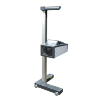
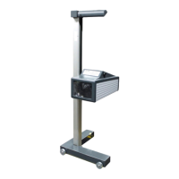
Use a forklift to position the display unit.
 Loading...