Maiman Electronics SF8025, SF8075, SF8150, SF8300
10
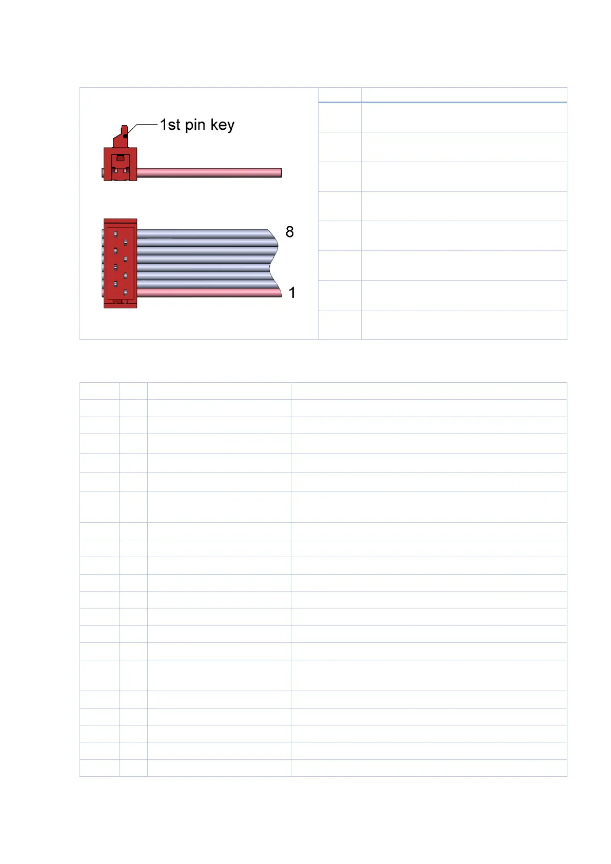
Digital control connector
Wurth WR-MM 690157000872 or TE Connectivity 215083-8
Interlock (duplicates pin 15 of analogue
control connector)
Crowbar status (duplicates pin 5 of
analogue control connector)
GND (connected to Vin- terminal)
Analogue control connector
Wurth WR-MM 6901 5700 20 72 or TE Connectivity 2-215083-0
HIGH = operates, LOW = stop. Internally pulled down.
HIGH = operates, LOW = stop. Internally pulled down.
HIGH = fault, LOW = normal operation.
HIGH = fault, LOW = normal operation.
Auxiliary +2.5V power supply.
Up to 10mA output current capability.
0-2.5V = 0-MAX current at the output.
0-2.5V = 0-MAX current at the output.
Open = locked; Low = operates.
Internally pulled up.
Connect NTC thermistor 10k between this pin and GND.
Connected to pin 4 of Butterfly.
Connected to pin 3 of Butterfly.