Do you have a question about the Major tech MT350 and is the answer not in the manual?
Tester displays voltage (P-E) per second. Proceed only if voltage is expected.
3 LED indicators show line status; third LED lights up when reversed.
Tester cuts and locks if resistor temperature is high, displays "Temperature is High".
Tester stops test if P-E voltage exceeds 250V, displays "250V".
Displays flag "i" when battery voltage drops below operating voltage.
Pressing "test" key displays result for 5s, then voltage.
0°C to 40°C (32°F to 104°F) and Humidity below 80% RH.
-10°C to 60°C (14°F to 140°F) and Humidity below 70% RH.
Powered by 6 x AA batteries; dimensions are 200(L) x 92(W) x 50(H) mm.
Approx 700g including battery.
Specifies ranges, resolutions, test times, and accuracies for loop resistance measurements.
Specifies ranges, resolutions, test times, and accuracies for PSC measurements.
Specifies the range and accuracy for AC voltage measurements.
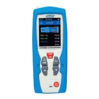
The main screen for displaying test results and parameters.
Button to activate the display backlight for low-light conditions.
LED indicators for line status (P-E, P-N, reverse polarity).
The primary button to initiate a loop or PSC test.
Selects the measurement range and mode (e.g., OFF, Loop, PSC).
Port for external power and a hook for hanging the meter.
Cover for accessing the battery compartment.
The Major Tech MT350 is a robust and reliable loop impedance and prospective short circuit (PSC) tester, designed for electrical professionals to ensure the safety and compliance of electrical installations. This instruction manual provides comprehensive guidance on its operation, features, and maintenance, emphasizing safety as a paramount concern.
The MT350 primarily functions as a loop impedance and PSC tester. It is engineered to measure the impedance of the earth fault loop and calculate the prospective short circuit current, which are critical parameters for verifying the effectiveness of protective devices in an electrical system. The device is specifically designed for use in AC230V +10% -15% (50Hz) systems.
Before any testing, the MT350 performs a crucial "Lines test" to check the state of the connected wires. This involves three LED indicators: P-E (Phase-Earth), P-N (Phase-Neutral), and a reverse P-N LED. The correct wiring state is indicated by the P-E and P-N LEDs lighting up, while the reverse P-N LED should not light. If the wiring is incorrect, the tester warns the user not to proceed, ensuring safety and preventing erroneous readings.
A fundamental aspect of its operation is the "Voltage test." Upon connection to the power supply, the LCD continuously updates the P-E voltage. This real-time voltage display allows the user to confirm that the supply voltage is within the expected range before initiating any further tests. An unusual or unexpected voltage reading serves as a critical warning, prompting the user to investigate the power source and refrain from proceeding with the tests.
For "Loop test" measurements, the user selects an appropriate range (20Ω, 200Ω, or 2000Ω) using the rotary function switch. After pressing the "TEST" button, the LCD displays the loop impedance value and its unit. The tester emits a single beep upon completion of the test. To achieve the most accurate readings, the manual advises selecting the lowest possible range. A flashing "i" flag on the LCD indicates that the tester's internal resistor temperature is high, prompting the user to disconnect the tester and allow it to cool down.
Similarly, for "Prospective Short Current test," the user selects a range (200A, 2000A, or 20kA). After pressing the "TEST" button, the LCD displays the PSC value and its unit, accompanied by a single beep. As with loop impedance testing, selecting the lowest possible range is recommended for better accuracy. A flashing "i" flag again signifies high internal resistor temperature, requiring the tester to be disconnected and cooled.
The MT350 incorporates several protective features to ensure both user safety and the longevity of the device. An "Over heat protect" mechanism activates if the internal resistor temperature becomes too high, causing the tester to cut off and lock. The LCD will display "Temperature is High" and flash the "i" flag. An "Overload protect" feature prevents damage if the P-E voltage exceeds 250V; in such a scenario, the tester stops the test, and the LCD flashes "250V."
The device's "Test mode" ensures that test results are displayed for a duration of 5 seconds before reverting to the voltage display, allowing ample time for observation.
The MT350 is designed for ease of use with a clear digital display and intuitive controls. The rotary function switch allows for straightforward selection between different test ranges for loop impedance and PSC, as well as the "OFF" position.
The "TEST" button is prominently located for initiating measurements. A "Backlight Button" enhances visibility of the digital display in poorly lit environments. Three dedicated LEDs (P-E, P-N, and P-N REVERSE Light) provide immediate visual feedback on the wiring status, which is crucial for safe and accurate testing.
The device is portable, powered by six AA batteries, making it suitable for fieldwork. A "Low Battery Indication" (a flashing battery flag) alerts the user when the battery voltage drops below the operating threshold, ensuring that tests are not performed with insufficient power, which could affect accuracy.
A "Pothook" is included, suggesting the device can be conveniently hung during use, freeing up the user's hands. The "POWER Jack" indicates an option for external power, though the primary power source is batteries.
The manual emphasizes the importance of following safety information, including not applying signals exceeding maximum limits, inspecting the meter and test leads for damage, and exercising extreme caution around bare conductors. It also highlights that the meter should only be used as specified to maintain its protective capabilities.
Maintenance of the MT350 primarily involves battery replacement. The manual provides clear, step-by-step instructions for this process. When the low battery symbol appears on the LCD, the six 1.5V 'AA' batteries need to be replaced.
The procedure involves:
The device is protected by double insulation or reinforced insulation, as indicated by the safety symbol, which contributes to its safety and reduces the need for extensive internal maintenance. The manual also states that when servicing, only specified replacement parts should be used, underscoring the importance of maintaining the integrity of the device's design. The MT350 complies with EN-61010-1 and carries the CE mark, indicating adherence to European safety standards.
The operating and storage temperature and humidity ranges are provided, guiding users on suitable environmental conditions to ensure optimal performance and longevity of the device. Operating within these specified ranges helps prevent damage and maintains measurement accuracy.
| Diode Test | Yes |
|---|---|
| Continuity Buzzer | Yes |
| Data Hold | Yes |
| Power Source | 9V battery |
| Operating Temperature | 0°C to 40°C |
| Storage Temperature | -10°C to 50°C |
| Display | LCD |
| Measurement Range | See individual parameters |
| Accuracy | See individual parameters |
| Resolution | Depends on range |