Do you have a question about the Major tech MTD75T and is the answer not in the manual?
Explains safety symbols, potential hazards, and double insulation indicators.
Crucial notes and warnings regarding input ranges, function switch usage, and measurement precautions.
Important cautions to prevent damage, shock, injury, or death during meter use.
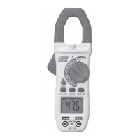
Labels and descriptions of all physical parts of the clamp meter.
Explains display symbols and lists the accessories provided with the meter.
Details accuracy, range, and resolution for various measurement functions.
Information on operating temperature, humidity, battery life, and safety compliance.
Step-by-step guide for AC and DC current measurements using the clamp.
Instructions for performing AC and DC voltage measurements with test leads.
Procedures for measuring resistance and capacitance with the meter.
Steps for measuring frequency and temperature using the appropriate probes/settings.
How to perform continuity, diode, and non-contact voltage tests.
Guide to using HOLD, flashlight, and LCD backlight functions for enhanced usability.
How to use range settings and manage automatic power-off functionality.
Guidelines for cleaning, storage, and replacing the meter's batteries.
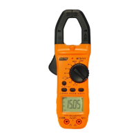
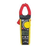
The MTD75T is an 800A AC/DC True RMS Digital Clamp Meter, designed for a wide range of electrical measurements. This versatile instrument combines several functions into a single, portable device, making it suitable for both professional and DIY use.
The MTD75T primarily functions as a clamp meter, allowing for non-contact measurement of AC and DC current up to 800A. This is achieved by clamping the meter's jaws around a single conductor, eliminating the need to break the circuit. In addition to current measurement, the device also offers comprehensive voltage measurement capabilities for both AC and DC circuits, up to 1000V DC/AC.
Beyond current and voltage, the MTD75T provides a suite of other essential measurement functions:
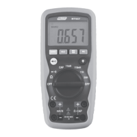
The meter features a rotary function switch for easy selection of the desired measurement mode. An LCD display shows the measurement readings and various icons indicating the active mode, data hold status, auto-range, and battery level.
The MTD75T is designed for ease of use and safety. Before any measurement, it is crucial to set the function switch to the appropriate position.
For AC and DC Current Measurements, ensure test leads are disconnected. Select the 'A' range on the rotary switch. For DC current, press the DCA Zero button to zero the display. Use the SELECT button to choose between AC and DC. Open the clamp jaws using the trigger and enclose only one conductor, centering it for optimal results. The reading will then appear on the LCD.
AC and DC Voltage Measurements require inserting the black test lead into the COM terminal and the red test lead into the V/Ω terminal. Set the function switch to the V~ for AC or V for DC position. Connect the test leads in parallel to the circuit under test, and the voltage reading will be displayed.
Resistance Measurement involves inserting test leads into the COM and V/Ω terminals, setting the function switch to the appropriate position, and using the SELECT button to choose Ω. Touch the probe tips across the circuit or component. For accurate readings, it's best to disconnect one side of the device under test.
For Capacitance Measurement, follow the same test lead insertion and function switch selection as resistance, but ensure the capacitor is discharged before testing. Use the SELECT button to choose nF.
Frequency Measurement also uses the COM and V/Ω terminals. Set the function switch to the Hz position. Touch the probe tips across the circuit or component, ideally with one side disconnected.
Temperature Measurements are performed by setting the function switch to °C/°F and inserting the Type K Temperature Probe into the COM and V/Ω jacks, observing polarity. Touch the probe head to the device under test and wait for the reading to stabilize. The SELECT button toggles between °F and °C.
Continuity Measurements involve inserting test leads into COM and V/Ω, setting the function switch to the continuity position, and using the SELECT button to choose the continuity icon. If resistance is less than 50Ω, an audible buzzer will sound.
Diode Measurements use the same test lead setup. Set the function switch to the diode position and use the SELECT button to choose the diode icon. Touch the probe tips to the diode, noting the reading, then reverse polarity and note the reading again to assess diode functionality.
The Non-Contact AC Voltage (NCV) Test is a safety feature. Touch the probe tip to a live conductor or the live side of an electrical outlet. If AC voltage is present, a red LED light will illuminate. It's important to test on a known live circuit first to verify proper operation.
The meter includes a Data Hold function, activated by pressing the HOLD button, which freezes the current reading on the LCD. The HOLD icon will appear. Pressing it again returns to normal operation.
For improved visibility, the MTD75T features an LCD backlight and an LED flashlight. Both can be turned on by pressing the Select Key button for 3 seconds and turned off by pressing it again for 3 seconds. They operate simultaneously.
The RANGE button allows users to switch between auto-ranging and manual ranging modes. In manual mode, pressing the RANGE key changes the measuring range. Holding the RANGE key for more than 1 second exits manual mode.
An Auto Power Off (APO) feature conserves battery life by automatically turning off the meter after approximately 15 minutes of inactivity. To reactivate, turn the rotary function switch to OFF and then to the desired function range. The APO function can be canceled by pressing the SELECT button while turning on the power with the rotary switch.
Proper maintenance ensures the longevity and accuracy of the MTD75T.
| Model | MTD75T |
|---|---|
| Category | Measuring Instruments |
| Type | Digital Multimeter |
| Diode Test | Yes |
| Continuity Test | Yes |
| DC Voltage Ranges | 200mV, 2V, 20V, 200V |
| AC Voltage Ranges | 200V |
| DC Current Ranges | 200µA, 2mA, 20mA, 200mA, 10A |
| Resistance Ranges | 200Ω, 2kΩ, 20kΩ, 200kΩ, 2MΩ |
| Display | 3 1/2 Digit LCD |
| Temperature Range | 0°C - 40°C |
| Accuracy | ±(0.5% + 2 digits) |
| Probe Type | Standard |
| Battery | 9V |