Do you have a question about the Makita 4329 and is the answer not in the manual?
This tool can be operated with an orbital or a straight line (up and down) cutting action.
Loosen the bolt on the back of the base with the hex wrench.
With the base tilted, you can make bevel cuts at any angle between 0° and 45° (left or right).
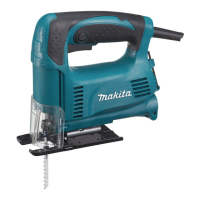
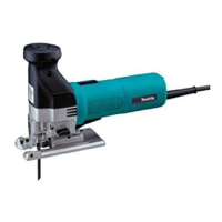
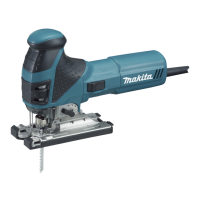
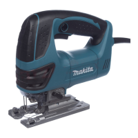
This document describes the Makita Jig Saw models 4326, 4327, 4328, 4329, 4326M, and 4327M, providing instructions for safe operation, assembly, and maintenance.
The Makita Jig Saw is designed for sawing wood, plastic, and metal materials. Its extensive accessory and saw blade program makes it suitable for various purposes, including curved or circular cuts. The tool operates on a single-phase AC supply and is double-insulated, allowing use from sockets without an earth wire.
For models 4328/4329, the tool offers an adjustable cutting action, allowing operation with either an orbital or a straight-line (up and down) cutting action. The orbital cutting action thrusts the blade forward on the cutting stroke, significantly increasing cutting speed. The cutting action can be changed by turning a lever to the desired position, with options for small, medium, and large orbit for different materials and cutting speeds. A straight-line cutting action (position 0) is recommended for mild steel, stainless steel, plastics, and for clean cuts in wood and plywood. Small orbit (position I) is suitable for mild steel, aluminum, and hard wood. Medium orbit (position II) is for wood, plywood, aluminum, and mild steel. Large orbit (position III) is for fast cutting in wood and plywood.
The tool features a switch trigger for starting and stopping, and a lock button for continuous operation. Models 4327/4327M/4328/4329 include a speed adjusting dial, which allows the tool speed to be infinitely adjusted between 500 and 3,100 strokes per minute. Higher speeds are achieved by turning the dial towards number 6, and lower speeds towards number 1. The appropriate speed depends on the type and thickness of the workpiece; higher speeds generally result in faster cuts but may reduce blade service life.
An adjusting roller is present on models 4326/4326M/4327/4327M. This roller helps guide the blade and ensure proper cutting. It can be adjusted by loosening a bolt on the back of the base with a hex wrench, moving a retainer so the roller lightly contacts the blade, and then tightening the bolt.
A dust cover is provided to prevent chips from flying during operation. It should be lowered for most cuts but raised all the way when making bevel cuts.
General Operation: Always hold the base flush with the workpiece to prevent blade breakage. When cutting curves or scrolling, advance the tool very slowly to avoid slanted cutting surfaces and blade breakage. Before starting a cut, turn the tool on without the blade contacting the workpiece and wait until the blade reaches full speed. Then, rest the base flat on the workpiece and gently move the tool forward along the marked cutting line.
Blade Installation and Removal: To install a blade, loosen the bolt on the blade holder counterclockwise using the hex wrench. Insert the blade with teeth facing forward into the blade holder as far as it will go, ensuring the back edge fits into the roller. Then, tighten the bolt clockwise to secure the blade. To remove the blade, reverse this procedure. Only B type blades should be used for models 4326/4327/4328/4329, and only Makita type blades for models 4326M/4327M, to ensure proper tightening and prevent serious injury.
Bevel Cutting: The base can be tilted to make bevel cuts at any angle between 0° and 45° (left or right). To adjust, loosen the bolt on the back of the base with the hex wrench. Position the base so the bolt is in the center of the cross-shaped slot. Tilt the base to the desired bevel angle, indicated by graduations on the motor housing edge, then tighten the bolt to secure the base. The dust cover must be raised all the way for bevel cuts.
Front Flush Cuts: For front flush cuts, loosen the bolt on the back of the base with the hex wrench and slide the base all the way back. Then tighten the bolt to secure the base.
Cutouts: Cutouts can be made by boring a starting hole or by plunge cutting. For internal cutouts without a lead-in cut from an edge, pre-drill a starting hole of 12 mm or more in diameter, then insert the blade to begin the cut. For plunge cutting, tilt the tool up on the front edge of the base with the blade point just above the workpiece surface. Apply pressure to prevent the base from moving when switching on the tool, then gently lower the back end of the tool slowly. As the blade pierces the workpiece, slowly lower the base onto the surface, and complete the cut normally.
Finishing Edges: To trim edges or make dimensional adjustments, run the blade lightly along the cut edges.
Metal Cutting: When cutting metal, always use a suitable coolant (cutting oil) to prevent significant blade wear. Greasing the underside of the workpiece can be an alternative to using a coolant.
Dust Extraction: For clean cutting operations, the tool can be connected to a Makita vacuum cleaner. Insert the vacuum cleaner hose into the hole at the rear of the tool and lower the dust cover before operation. Note that dust extraction cannot be performed when making bevel cuts.
Rip Fence (Optional Accessory): The rip fence (guide rule) can be used for straight cuts and circular cuts. For straight cuts, insert the rip fence into the rectangular hole on the side of the base with the fence guide facing down. Slide it to the desired cutting width and tighten the bolt. This ensures fast, clean, straight cuts for widths of 160 mm or less.
For circular cuts of 170 mm or less in radius, insert the rip fence into the rectangular hole on the side of the base with the fence guide facing up. Insert the circular guide pin through one of the holes on the fence guide, screw the threaded knob onto the pin, and slide the rip fence to the desired cutting radius. Tighten the bolt and move the base all the way forward. Specific blade types (B-17, B-18, B-26, B-27 for models 4326/4327/4328/4329, and No.6, No.7, No.16, No.17 for models 4326M/4327M) are recommended for circular cuts.
Anti-splintering Device (Optional Accessory): For splinter-free cuts, an anti-splintering device can be used. For steel base types, move the base all the way forward and insert the device between the two protrusions of the base. For aluminum base types, move the tool base all the way forward and fit the device from the back of the tool base. If using a cover plate, install the anti-splintering device onto the cover plate. Note that the anti-splintering device cannot be used when making bevel cuts.
Cover Plate for Aluminum Base (Optional Accessory): The cover plate protects sensitive or delicate surfaces from damage when cutting decorative veneers, plastics, etc. It fits on the back of the tool base.
General Maintenance: Always ensure the tool is switched off and unplugged before performing any inspection or maintenance. Never use gasoline, benzine, thinner, alcohol, or similar substances, as they can cause discoloration, deformation, or cracks.
Lubrication: The roller should be lubricated occasionally.
Repairs and Adjustments: To maintain product safety and reliability, all repairs, carbon brush inspection and replacement, and any other maintenance or adjustment should be performed by Makita Authorized Service Centers, using only Makita replacement parts.
Hex Wrench Storage: The hex wrench can be stored on the tool as shown in the figure to prevent it from being lost when not in use.
| Output power | 450 W |
|---|---|
| Power source | AC |
| No-load stroke rate | 3100 spm |
| Cutting depth in wood | 65 mm |
| Cutting depth in non-alloyed steel | 6 mm |
| Saw blade included | Yes |
| Weight | 1900 g |
|---|