P 4/ 18
Repair
[3] DISASSEMBLY/ASSEMBLY
[3] -1. Base (cont.)
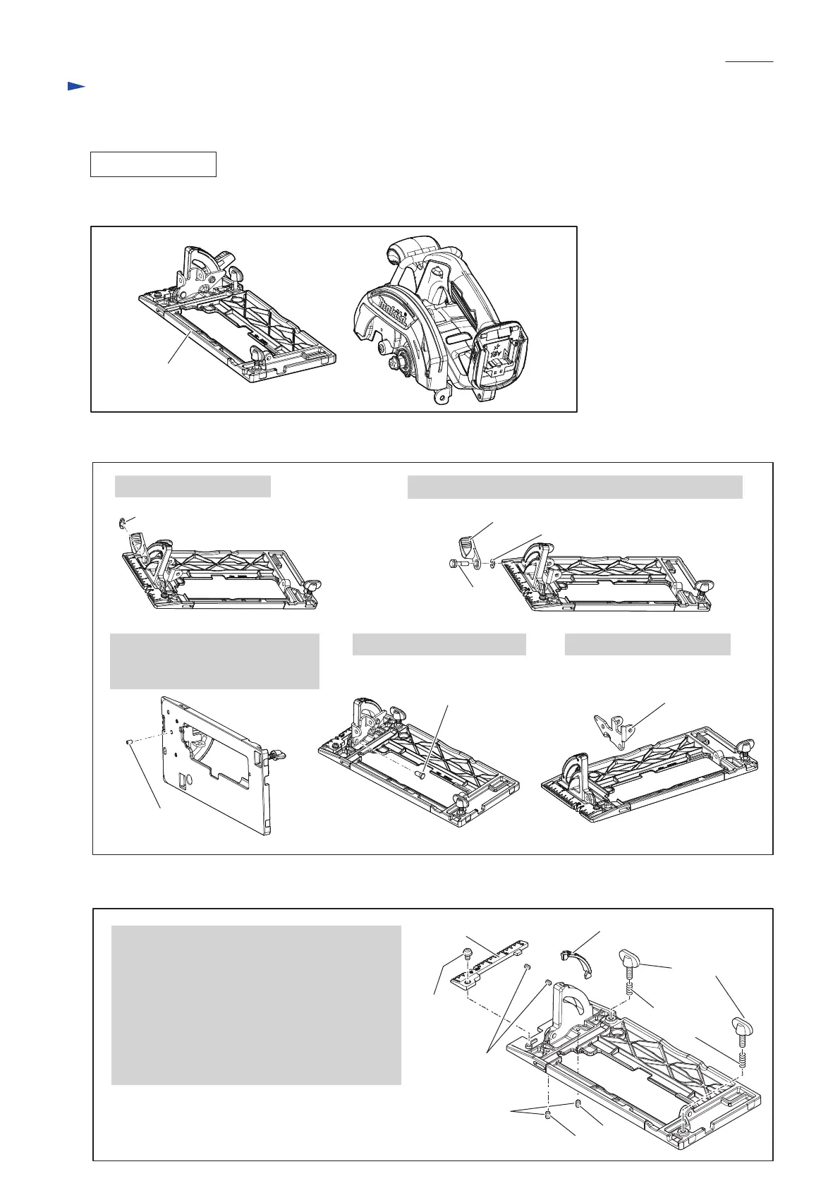
DISASSEMBLING
(1) Separate Base section from the machine. (Fig. 4)
(2) Disassemble Angular guide section as drawn in Fig. 5.
(3) Disassemble Base section as drawn in Fig. 6.
3. Remove M5x8 Hex socket
head set screw which functions
as a stopper for 6-7 Shoulder pin.
4. Remove 6-7 Shoulder pin.
1. Remove Stop ring E-8.
2. Remove M6x20 Hex bolt, Lever 45 and Flat washer 6.
5. Remove Angular guide.
Fig. 4
Fig. 5
Fig. 6
Base section
6-7 Shoulder pin
Top guide
Bevel guide
Compression
spring 6
M5x20
Thumb screw
M5x8 Hex socket
head set screw
M4x6 Hex socket
head set screw
Note in Disassemble:
Be careful not to lose four M5x8 Hex socket head
set screws used for the following:
* stopping 6-7 Shoulder pin of
Depth guide. (See the top right in Fig. 3.)
* stopping 6-7 Shoulder pin of Angular guide.
(See the bottom left in Fig. 5.)
* (a) adjusting 45° bevel
* (b) adjusting 90° bevel
(a)
(b)
M5x8 Pan
head screw
Stop ring E-8
M5x8 Hex socket
head set screw
Angular guide
M6x20 Hex bolt
Lever 45
Flat washer 6

 Loading...