Wiring diagram
P 10 /10
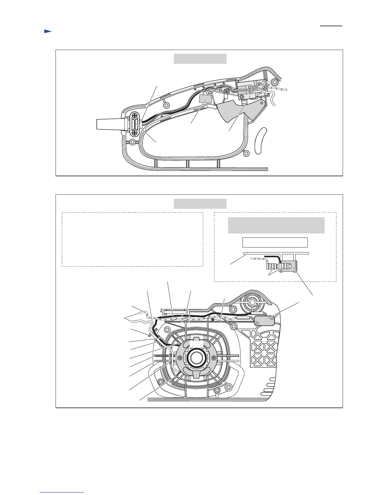
Fig. 20
(to main switch)
Field
Brake switch
A. Field Lead Wire (black)
Connecting lead wire (orange)
B. Field Lead Wire (white)
Lead wire holder
Lead wire holder
Lead Wire Holder
Rib F
Rib G
Rib D
Rib E
Rib C
Rib B
Rib A
Wall of
housing set (L)
Recectaples
Top View of Bake Switch
The recectaples have to face the wall of
housing set (L).
A. Field Lead Wire (black) to Brake Switch
Route it between rib A and rib B.
B. Field Lead Wire (white) to main switch
Route it between rib C and rib D.
Route these lead wires between rib F and rib G, and then
put them into lead wire holders.
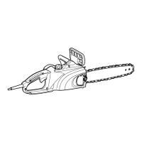
Motor Section
Handle Section
Main Switch
Noise Suppressor
Strain Relief
to Field
Power Supply Cord
Put noise suppressor into the space
between strain relief and main switch.
to Brake switch
Fig. 21
 Loading...