P 7 /10
Repair
[3] DISASSEMBLY/ASSEMBLY
[3] -2. Brake Mechanism and Armature (cont.)
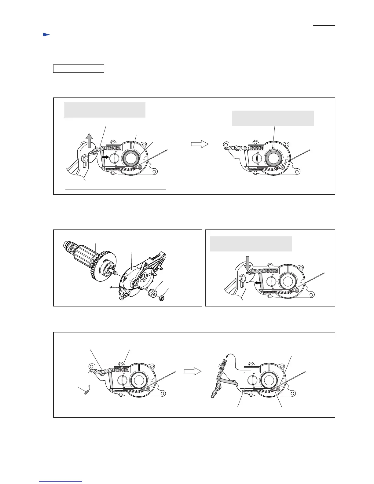
Fig. 12
Fig. 13
Fig. 15
DISASSEMBLING
6) Unlock the Kick back brake by pulling Link plate complete in the direction of the gray arrow with adjustable pliers.
(Fig. 12)
7) Armature can now be separated from Bearing holder as illustrated in Fig. 13.
8) Remove the tension force of Compression spring 9 from Link plate complete by pulling Link plate complete with
pliers in the direction of the gray arrow with adjustable pliers. (Fig. 14)
9) By removing Pin 5, Link plate complete and Compression spring 9 can be separated from Bearing holder. (Fig. 15)
Link plate complete
drum portion of Armature
Bearing Holder viewed form Armature Side
Hex nut M8
Spur gear 12
Bearing holder
Armature
Fig. 14
Link plate complete Compression spring 9
Brake band
Tapping screw 4x18,
securing Brake band
Brake ring
Link plate complete moves
in the direction of the black arrow.
Link plate complete moves
in the direction of the black arrow.
Brake band is loosened to unlock
the drum portion of Armature.
Brake band
Pin 5
 Loading...