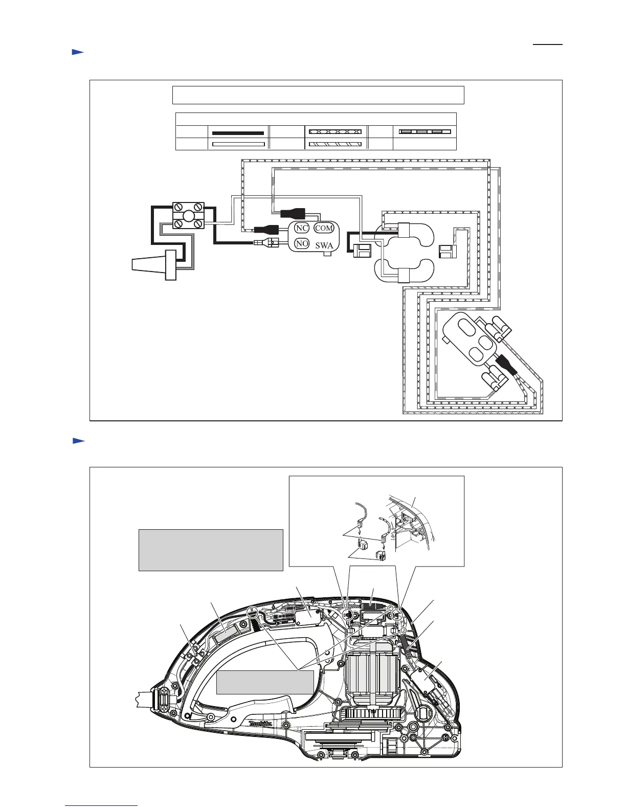
Circuit diagram
Color index of lead wires' sheath
Black
For the Market where the Radio interference suppression is not required.
White
Red
Orange
Yellow
Terminal block
Switch A
Switch A: Switch operated with Switch lever A in Main grip
Switch B: Switch operated with Switch lever B in Front grip
Switch B
Field
Power supply
cord
NC
NO
COM
Fig. D-1C
Housing L
Brush holder
Fix the Lead wires in
these Lead wire holders.
Receptacle
Terminal block
Housing L
Noise suppressor
Locate Noise suppressor and Choke
coils in the positions drawn below
when they are used.
Switch A
Choke coil
Choke coil
Switch B
Wiring diagram
Fig. D-2
Connect Receptacles in this direction.
P 7/ 7
 Loading...