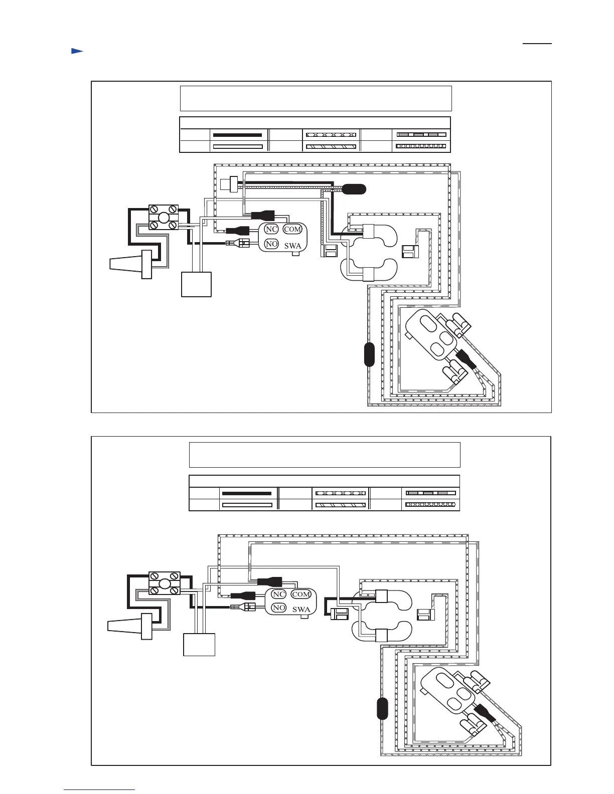
Circuit diagram
Fig. D-1A
220 - 240V
For the Market where the Radio interference suppression is required.
Choke coil
Choke coil
Noise
suppressor
Switch A
Switch A: Switch operated with Switch lever A in Main grip
Switch B: Switch operated with Switch lever B in Front grip
Switch B
Field
Power supply
cord
Color index of lead wires' sheath
Black
White
Red
Orange
Yellow
Purple
Color index of lead wires' sheath
Black
White
Red
Orange
Yellow
Purple
NC
NO
COM
Terminal block
110 - 127V
For the Market where the Radio interference suppression is required.
Choke coil
Noise
suppressor
Switch A
Terminal block
Switch A: Switch operated with Switch lever A in Main grip
Switch B: Switch operated with Switch lever B in Front grip
Switch B
Field
Power supply
cord
NC
NO
COM
Fig. D-1B
P 6/ 7
 Loading...