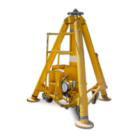
Model: 95P10AR
Two Stage Hydraulic Aviation Floating Auto-Retract Axle Jack
S/N 263 and Up
12/2018 | Rev. 01 Page | 6
5.0 OPERATION
5.1 PRE OPERATION INSPECTION
Each time the jack is to be used, inspect the following:
1. Check jack structure for rigidity. Make sure all bolts are tightened.
2. Check hydraulic line connections for leaks. Tighten as required.
3. Check for hydraulic fluid leaks around the cylinder assembly, reservoir, air pump and hand pumps.
4. Check hand pumps for proper operation.
5. Check caster wheels for proper operation.
6. Check reservoir fluid level with jack plungers fully retracted.
7. Check tow handle let-down feature for proper operation.
5.2 OPERATING PROCEDURES
1. Position the jack under the appropriate jacking pad of the aircraft. Positioning of tow handle in either full-up or full-down
position will lower jack for minimum ground clearance.
CAUTION!
Do not extend extension screw against aircraft jack pad with the plungers fully retracted.
2. Raise the extension screw by turning counterclockwise until the ship adapter is 1/2" to 1" from aircraft jacking pad
or as far as the screw will travel (4.62 inches maximum).The optional 2 inch extender (48 ton maximum capacity) can be
used when jacking 747 NLG. Place the extender over the fully raised extension screw and verify that it sits flat on the
inner plunger before jacking.
3. Close the release valve located on control console.
CAUTION!
On jack equipped with air pump, air relief valve must be installed at all times. If air relief valve is removed,
it is possible to over pressurize the pneumatic system which could cause equipment failure and possible
bodily injury.
4. On jack equipped with air pump, connect air supply (90-110 psig) to the 3/8 NPT air inlet (for low flow air pump) or
the 1/2 NPT air inlet (for high flow air pump) near the air valve on the control console (A minimum of 28 scfm is
required for the low flow air pump or a minimum of 56 scfm is required for the high flow air pump). Air relief valve
must be properly installed. Do not attempt to remove air relief valve.
5. The jack is equipped with two hand pumps. One with 3/4 inch diameter pump plunger for rapid raising of jack
plungers under low pressure and one with 7/16 inch diameter pump plunger for high pressure operation. The hand
pumps can be operated by placing pump handle over the end of the pump fulcrum and operating either the low or
high pressure hand pump.
6. Operate air valve or either hand pump to raise plungers until the ship adapter contacts the jacking pad.
Note: A small amount of fluid wetting is normal on manual hand pump plungers. Periodically clean to remove
accumulated grease or foreign material.
7. Insure ship adapter and jacking pad are correctly mated.
8. To raise the load:
a. Operate the air valve or either hand pump as required.
b. Do not lift a load greater than the rated capacity of 95 tons (86.2 m. tons). The approximate load being lifted
can be read in tons on the load gauge. Read load on lower stage scale when only outer plunger is extended.
Read load on upper stage scale when inner plunger is extended. Fluid pressure in psig may be read on outer
scale for gauge calibration.
9. To lower the load:
a. Slowly open the release valve to lower the load. The speed of lowering is controlled by the amount the release
valve is open. Note: It is important to lower the load slowly. Retracting the plungers too fast will cause the
velocity fuse to close and prevent plungers from retracting. Should this occur, close release valve, operate
either pump to reset velocity fuse and then open release valve again slowly. Plungers will retract fully,
automatically.
10. Lower extension screw. Close release valve. Cover jack when not in use.