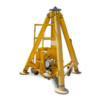
Model: 95P10AR
Two Stage Hydraulic Aviation Floating Auto-Retract Axle Jack
S/N 263 and Up
12/2018 | Rev. 01 Page | 8
7.0 MAINTENANCE
7.1 SERVICING
Servicing the jack consists primarily of the following:
1. When in use, the reservoir should be kept at the proper hydraulic fluid level. Check with plungers fully retracted.
2. Grease casters and wheel as required.
3. Lubricate hand pump pivot pins and tow handle linkage.
4. On jack equipped with pump lubricator, fill lubricator with SAE #10 oil.
5. If the jack has been put into storage or has not been used, the plungers must be fully extended and retracted every 90
days to exercise the seals. A portion of the lift should be operated by the air pump and a portion by the hand pumps.
6. Procedure to verify or recharge GN2 pressure in accumulator (Note: Under normal operating conditions, the accumulator
system should not require servicing for 3 years):
a. Open release valve on control console.
b. Open accumulator shutoff valve located underneath the frame.
c. Attach accumulator test gauge assembly, Malabar tool P/N 872845 (0-300 psig) to accumulator charging valve
located on top of the accumulator. Verify test gauge reads 140 ± 5 psig. If necessary, charge accumulator using GN2
until test gauge reads 140 ± 5 psig.
d. Close accumulator shutoff valve.
e. Close release valve on control console.
f. Disconnect Malabar tool P/N 872845 from accumulator.
g. Immediately proceed to step 7 below.
7. Procedure to recharge hydraulic fluid pressure in accumulator:
a. Open release valve on control console.
b. Open accumulator shutoff valve located underneath the frame.
c. Remove cap from test port located behind control console.
d. Attach hose and test gauge assembly, Malabar tool P/N 872839 (0-600 psig) to test port.
e. Close release valve on control panel.
f. Operate air pump or either hand pump to extend plungers to near full extended height. Now slowly operate hand
pump only until plungers just reach full extension. At this point pressure will build up rapidly so proceed cautiously.
Slowly operate hand pump until test gauge reads 340 ± 10 psig.
CAUTION!
Rapid pumping at this time will over pressurize and damage the test gauge.
g. Firmly close accumulator shutoff valve. Verify that the test gauge reads 340 ± 10 psig just prior to the valve fully
seating.
h. Open release valve on the control console.
i. Remove hose and test gauge assembly tool P/N 872839.
j. Replace cap on test port.
8. Procedure to verify or adjust accumulator relief valve:
CAUTION!
The accumulator relief valve, located under the reservoir, should not be disturbed unless absolutely
necessary. The relief valve is set at the factory to bypass hydraulic fluid to atmosphere at 550 ± 25 psig.
a. Open release valve on control console.
b. Open accumulator shutoff valve located underneath the frame.
c. Remove cap from test port located behind the control console.
d. Attach hose and test gauge assembly tool, Malabar P/N 872839 (0-600 psig) to test port.
e. Remove accumulator relief valve deflector cap.
f. Close release valve on control panel.
g. Operate air pump or either hand pump to extend plungers to near full extended height. Now slowly operate hand
pump only until plungers just reach full extension. At this point pressure will build up rapidly, so proceed cautiously.
Slowly operate hand pump and verify accumulator relief valve by-passes hydraulic fluid to atmosphere at 550 ± 25
psig.
CAUTION!
Rapid pumping at this time will over pressurize and damage the test gauge.
h. If adjustment is required, insert a standard 5/32 inch hex key wrench into the locking screw.
i. Break loose locking screw counterclockwise until the hex key wrench slides into the adjusting screw.
j. Turn both screws together to the desired by-pass pressure of 550 ± 25 psig. (Clockwise increases bypass pressure).
k. Retract hex key wrench into the locking screw.
l. Lock locking screw against adjusting screw by turning clockwise.
m. Replace accumulator relief valve deflector cap.
n. Lower pressure reading to 340 ± 10 psig by opening release valve.